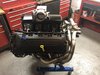
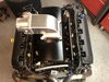
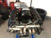
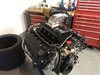
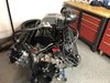
So the new part came today and even though my motor is not going to have that classic look, I think I like how it’s coming along.

You are using an out of date browser. It may not display this or other websites correctly.
You should upgrade or use an alternative browser.
You should upgrade or use an alternative browser.
My Have Found A Coyote Intake Solution
- Thread starter Norcoastal
- Start date
Dr. Bob Woods
Supporter
Steve, Will that fit under the rear window and rear deck? What about a filter, that might take up more space.
Bob Woods
Tornado GT40 in Texas
Bob Woods
Tornado GT40 in Texas
Steve, Will that fit under the rear window and rear deck? What about a filter, that might take up more space.
Bob Woods
Tornado GT40 in Texas
Hi Bob,
It’s gonna be tight. I think the MKII gives you a “little” more room, but it’s going to be close.
The air intake will go sideways so it wound cause any additional height.
In my opinion, it doesn't look right at all. It's better looking with the OEM intake.
Why not go for a custom made sheet metal intake with quad Webers, that would look as it should.
Why not go for a custom made sheet metal intake with quad Webers, that would look as it should.
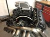
Put the engine in and mock it up. Looks cool
Mark
Mark
In my opinion, it doesn't look right at all. It's better looking with the OEM intake.
Why not go for a custom made sheet metal intake with quad Webers, that would look as it should.
I don’t like the stock manifold. What’s important to me is drive by wire. I can’t do drive by wire any other way. Also, 8 stacks are like 6 grand.
Put the engine in and mock it up. Looks cool
Mark
Thanks Mark
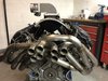
I think so also, when I add a cold air intake it will look better.
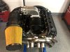
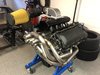
Mocked up the fuel rails. I think the black looks great.
I like the look. My car will be modern underneath and classic on the outside. This fits what I’m going for.
To be honest I’d prefer an 8 Stack, but like I said, it’s 6 grand that I can spend elsewhere.
I like the look. My car will be modern underneath and classic on the outside. This fits what I’m going for.
To be honest I’d prefer an 8 Stack, but like I said, it’s 6 grand that I can spend elsewhere.
Attachments
-
 08BBACFE-EE6E-434A-AB86-64B4383970DC.jpeg471 KB · Views: 532
 -
 870B9961-289F-42B0-99C9-6F87A0F80BBE.jpeg435.1 KB · Views: 484
 -
 6CF083C1-2FA2-4B4B-845A-85C4D833C9A6.jpeg418.5 KB · Views: 459
 -
 04BC0F2D-4595-464E-B51B-9904E69B098F.jpeg443.6 KB · Views: 837
 -
 6CFE6CF4-4DE1-4B38-AB14-AA147F4AD350.jpeg434.4 KB · Views: 474
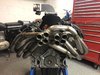
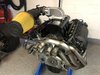
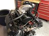
I was between a rock and a hard place. If it faced the back there was no room for an air intake. If it pointed towards the front, it would interfere with the headers.
My only option was on top and put the air intake towards the side.
My only option was on top and put the air intake towards the side.
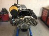
Here’s my chassis (Active Power) with a coyote engine from the Active Power site. Looks like I’ll have no trouble with the rear clamshell.
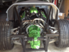
The other picture is my chassis that I bought. It had a green engine. The guy I bought if from kept the engine and sold me the chassis. Looks like he has an elevated manifold and there is still plenty of room.
I won’t know until I install the engine, but it seems like it should fit.
The other picture is my chassis that I bought. It had a green engine. The guy I bought if from kept the engine and sold me the chassis. Looks like he has an elevated manifold and there is still plenty of room.
I won’t know until I install the engine, but it seems like it should fit.
Attachments

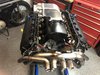
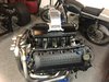
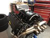
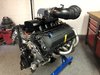
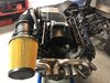
I’m done and I’m diggin it.
I get if many of you will hate this, but I love it and it’s totally functional and I can use all of the stock coyote senors and control pack and most importantly, the drive by wire pedal.
I get if many of you will hate this, but I love it and it’s totally functional and I can use all of the stock coyote senors and control pack and most importantly, the drive by wire pedal.
Attachments
-
 6C6B51C5-A7BC-4F68-AF55-B50AAEE3D0CD.jpeg461.8 KB · Views: 426
 -
 3C9C0D2F-B24C-45D9-AB1D-57BA0B927895.jpeg436.5 KB · Views: 425
 -
 521F4524-00C5-45ED-BAF3-2A2332E79F5C.jpeg453.7 KB · Views: 457
 -
 3398B002-15B9-42FF-BD28-02B048DDABF6.jpeg443.5 KB · Views: 456
 -
 6E75148D-6C99-4A1C-8CBB-03AEC61550A8.jpeg454.7 KB · Views: 432
 -
 471CA605-3896-4703-AE63-DD7D1CA41697.jpeg445.1 KB · Views: 461
That will work. Nice job
That will work. Nice job
Thanks Mark
What other goodies do you have there. I see gauges and expansion tank? How is the budget going.
Doing well. The body is having the inner panels fiberglass’s in right now in Ohio. Will have it shipped to NY probably in a week or so.What other goodies do you have there. I see gauges and expansion tank? How is the budget going.
Hello Steve,
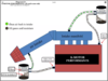
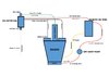
Interesting diagram that. A vendor proposing venting in to both locations. If you refer to this thread:
https://www.gt40s.com/threads/crankcase-ventilation-and-evap-system.52369/#post-526438
you’ll see my arrangement and query. Member Dimi pointed out that venting directly in to the manifold would upset the air / fuel mixture. Not wrong, as such, but not recommended.
I hasten to add that I am a newbie as far as modern car electronics are concerned and having to learn quickly. I’ve spent much more time slinging spanners at the dinosaur technology on my ’74 850 Norton Commando. No ECU or sensors there!
Anyway, in line with Dimi’s advice, I’m assembling the arrangement shown in the attached diagram. It would however, be more convenient to vent directly into the manifold.
Are there any more opinions on this issue?
Cheers, Lance
Attachments
Similar threads
- Replies
- 3
- Views
- 1K
- Replies
- 14
- Views
- 5K
- Replies
- 4
- Views
- 1K