New Lower Reverse A Arms

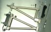
I just installed Ian Clark's famous lower arms for the CAV and they are fantastic.
Inspite of a bit of fabrication/welding and machining of the upper and lower clevis, they have allowed positioning of the rear tyres in the proper(centered) position inside the wheel well.
The quality and finish of the parts are first rate!

Congratulations on a nice product and worthwhile modification, Ian.


RHlowerRevArmsInSitu.jpg


extended upper and lower clevis:
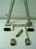
Upper_lowerClevis.jpg


a better shot:
RHLowerRevArmsInSitu2.jpg
 

Ian Clark

Supporter
Hi Ray,

Thanks for the posting. The new arms really do make a huge difference to the rear end on the early (pre s/n 100) cars.

The next batch of arms will be supplied with new clevis pins so the adapting to the original CAV parts won't be required. This will save owner/builders some work however the part price will go up:)

Cheers
 
lost the shot of the upper and lower clevis???

Here it is again as I'm quite proud of the welding job we did...

Upper_lowerClevis1.jpg


Now start working on a shock mount lowering kit, will you? /ubbthreads/images/graemlins/smile.gif /ubbthreads/images/graemlins/1poke.gif
 

Ian Clark

Supporter
Hey Ray,

You see that thick spacer between the coil spring and the two flat height adjuster nuts? Put that spacer in a lathe and cut it back to a half inch thick, leaving the inner ridge that the spring centers on of course. That'll buy you an inch at least:)
 

Ian Clark

Supporter
Here's a pic of the complete kit. This setup fits all early CAVs. The newest cars from Autofutura have revised uprights and a-arms, so this is a retrofit upgrade. Note: the original parts work well in a street only, modest power application.

The rubber bushes on the original arms have been replaced with genuine Aurora PFTE lined Monoballs and an Aurora PFTE lined Rod Ends for adjusting the toe setting.

All the tubing and the CNC machined bearing sleeves are 4130 DOM chrome moly. The one piece billet Mounting Block replaces a five piece weldment and is much stronger with no weight penalty.

The new clevis through bolt is 4340 heat treated with CNC threads, very tough stuff.

The finish is E-Nickle, electroless nickle plating, non invasive, plates inside the tubes as well and can be polished to a near chrome finish.

The new A-Arms also correct the wheelbase and increase anti squat geometry. All the friction of the bushes is eliminated as is adjusting the toe by shims. Very slick and functional. You can feel the difference even on the street:)
 

Attachments

  • 80704-RearA-ArmKit06.jpg
    80704-RearA-ArmKit06.jpg
    169.4 KB · Views: 338

Ian Clark

Supporter
Here's a pic of the original A-Arms with the Mounting Block disected for analysis. These work well in a stock application, although getting rid of the friction and compliance in the bushes is always a good thing.
 

Attachments

  • 80705-StockA-Armsb.jpg
    80705-StockA-Armsb.jpg
    115.5 KB · Views: 291

Howard Jones

Supporter
Here's a thought. Post the relevant measurements so that owners of other chassis types, I thinking GTD, would be able to figure out if they would work for them.

Sure would save a lot of work making our own.
 

Ian Clark

Supporter
Hi Howard,

That's kind of like giving away the store isn't it? Anyways, what's interchangeable between the CAV early mono cars and the GTD tube cars isn't likely to be much.

I could work backwards from accurate dimensions of your arms and see if we can work from our jigs and CNC files on hand. If the GTD guys want these too then I could get some economy of scale in the manufacturing, save some dough...

Be glad to tackle this for you...

Cheers
 

Howard Jones

Supporter
Ian, I thought you might say that but unless yours are a very close fit to other cars limmited dimensions wouldn't be worth stealing. Others wouldn't know if they would fit without measuring theirs anyway. The question would be, would the cost of the existing CAV A arm be a better alternative than making our own. I could make my own but I'm always looking for a less labor intensive/ cost effective way to do things.

All that really is needed is total length and outboard rod end spacing. The shock mounts look good as does the roll bar link pick up point. I wouldn't expect a cad drawing nor would it be needed to tell if they would be useful. Anyway I understand your point. I'm not sure mine wouldn't be the same.

Really nice work by the way. Oh and when I say I could make my own I didn't mean to say they would be as nice as yours. I would just use 3 rod ends and live with the adjustment issues.
 

Ian Clark

Supporter
Thanks Howard,

There are certainly simpler and less costly ways to make A-Arms with some kind of bearing inplace of the bushes. If you can fab up something for yourself that's great, it's all part of the kit car game. We're best at serving the guy who just wants to drive. Of course anything posted is bound to stimulate your grey matter:)

Cheers
 
[ QUOTE ]
Hey Ray,

You see that thick spacer between the coil spring and the two flat height adjuster nuts? Put that spacer in a lathe and cut it back to a half inch thick, leaving the inner ridge that the spring centers on of course. That'll buy you an inch at least:)

[/ QUOTE ]

I thought of that, but my hesitation was limiting compression shock travel at the new lowest setting. I should have measured full extension/compression while the shocks were off...

I'll do a search as I think Bob Childress did a mod to his shock mounts to achieve the lower height; not sure if it's applicable to my "classic" MONO29. Bob? Ping Bob? /ubbthreads/images/graemlins/confused.gif
 

Ian Clark

Supporter
Hi Ray,

The rubber snubbers on the shock shaft will prevent damage to the shock and acts like a rising rate spring if you bounce it up that far, so you should be OK.

Cheers
 
Back
Top