Howard Jones
Supporter
Here's what I've been doing the last couple of weeks.
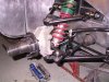
The problem we have with the front of the GTD chassis is nothing is adjustable, really. You can shim some things and move the others around in slots but neither really solves the problems. I began my GTD suspension journey at the rear with trying to address the huge camber change under bump problem and I believe I have made at least my car a lot better at the rear. This has caused me to really begin to feel the lack of camber for one and nearly no caster for the other at the front of my car. I have removed all the shims in an effort to increase camber somewhat and found that with all I can do the RF is .25 degree neg and the LF is about a 1/8th of a degree POSITIVE! To make matters worse the most caster I can get on either side is about a degree and a half neg.
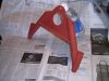
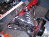
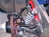
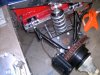
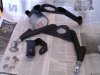
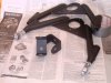
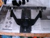
All of this pointed to new upper A-Arms and mounting points. As you can see the camber is adjustable. I made them 1/2" shorter and with the 1/4" I gain with the mounts, this should give me about a max camber of -3 degrees with the rod ends all the way into the bung . The mounts are offset to the rear and with the increased adjust-ability by spacing the rod end in the mounts, I believe I should be able to set the caster to a range of -1 to about -6 degrees.
I have also eliminated the slots. I have been having problems with the settings changing due to curbing the car at the track. The slots just don't work and I believe I will have solved that problem by drilling fixed mounting holes in the U-shaped mounts instead of slots.
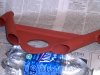
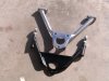
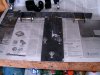
The bottom picture is the jig I had to make off of the original GTD A-Arm. What I did was copy the original part and move the 3 holes the upper ball joints bolts to inboard 1/2".
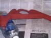
I should add that the material is 4130, was preheated before welding with the proper filler rod and then normalized as a complete assembly. I got the bungs from The Chassis Shop, the flat stock and tubing (.085 X 1) from Aircraft Spruce, and the rod ends from Jeg,s.
I did all the fitting and had a very good friend at work do the welding. It's amazing what you can do with a hacksaw and a 1/2 round file and a 3/8 drill motor. But then you gotta be "The cheap Italian" !!! to do it like this.
The problem we have with the front of the GTD chassis is nothing is adjustable, really. You can shim some things and move the others around in slots but neither really solves the problems. I began my GTD suspension journey at the rear with trying to address the huge camber change under bump problem and I believe I have made at least my car a lot better at the rear. This has caused me to really begin to feel the lack of camber for one and nearly no caster for the other at the front of my car. I have removed all the shims in an effort to increase camber somewhat and found that with all I can do the RF is .25 degree neg and the LF is about a 1/8th of a degree POSITIVE! To make matters worse the most caster I can get on either side is about a degree and a half neg.
All of this pointed to new upper A-Arms and mounting points. As you can see the camber is adjustable. I made them 1/2" shorter and with the 1/4" I gain with the mounts, this should give me about a max camber of -3 degrees with the rod ends all the way into the bung . The mounts are offset to the rear and with the increased adjust-ability by spacing the rod end in the mounts, I believe I should be able to set the caster to a range of -1 to about -6 degrees.
I have also eliminated the slots. I have been having problems with the settings changing due to curbing the car at the track. The slots just don't work and I believe I will have solved that problem by drilling fixed mounting holes in the U-shaped mounts instead of slots.
The bottom picture is the jig I had to make off of the original GTD A-Arm. What I did was copy the original part and move the 3 holes the upper ball joints bolts to inboard 1/2".
I should add that the material is 4130, was preheated before welding with the proper filler rod and then normalized as a complete assembly. I got the bungs from The Chassis Shop, the flat stock and tubing (.085 X 1) from Aircraft Spruce, and the rod ends from Jeg,s.
I did all the fitting and had a very good friend at work do the welding. It's amazing what you can do with a hacksaw and a 1/2 round file and a 3/8 drill motor. But then you gotta be "The cheap Italian" !!! to do it like this.
Attachments
Last edited: