Norfolk Tornado

More business trips and then keeping the family happy has minimised the amount of time working on the car.

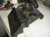
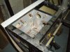
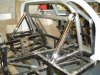
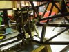
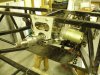
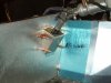
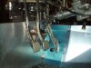
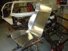
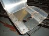
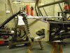
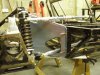
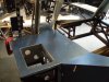
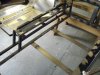
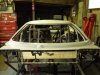
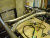
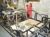
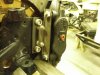
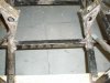
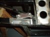
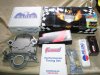
A removable engine bay cross-member has been added. A section of the chassis rail was cut out and a 3mm plate welded back in with a couple of captive nuts. This was originally cut out when the Rover mounts were removed and had to wait until the proposed oil pan (Moroso) arrived from Summit Racing, As a couple of braces were also added around the revised transmission cross-member, as well as the sill-top braces to support the aluminum top skin.

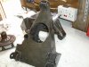
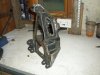
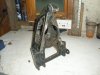
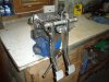
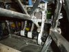
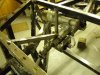
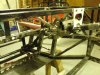
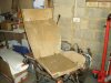
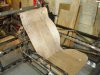
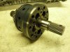
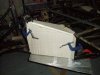
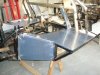
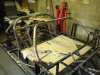
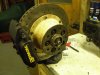
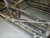
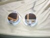
I’ve also spend many noisy hours with the grinder doing this and dressing the welds on the suspension arms prior to powder-coating. All the spacers for the rear suspension rose joints have been re-manufactured in stainless steel. These replace the combination of washers and bits of copper tube the original builder had used!

Regards
Andy
 

Attachments

  • P5250718.jpg
    P5250718.jpg
    41.9 KB · Views: 1,298
  • P5250723.jpg
    P5250723.jpg
    43.8 KB · Views: 1,337
  • P5260724.jpg
    P5260724.jpg
    50.4 KB · Views: 1,467
The business trips do sometimes have there uses, especially when going to Detroit and parts are pre-ordered from Summit for hand-carry back. The trip over to have a chat with Fran at RCR produced an even emptier wallet :laugh:

Regards
Andy
 

Attachments

  • P5020703.jpg
    P5020703.jpg
    56.1 KB · Views: 1,631
  • P5020704.jpg
    P5020704.jpg
    32.6 KB · Views: 1,705
They are fairly Bling! :drunk:

I cant bring myself to tone them them down a bit with a Scotchbrite pad. They're stay like this for a while, or until I fed up of polishing them.

Andy
 
The rear uprights have received a great deal of attention. Unfortunately the standard part from Tornado is leaves a lot to be desired, it may be light, but it’s no work of art. The previous owner hadn’t helped the matter by using an oxy-acetylene torch (gas-axe) to reposition the holes for a Scorpio bearing carrier. This had left a couple of mounting holes in virtually free space :evil:, so new metal had to be added around these.

The welds were also dressed back and well as the removal of unnecessary material (note the lower ‘ears’ have been cut back). Weld nuts have also been added to hold in the bearing retainers, making it much easier to strip down at a later date. I don’t believe that what I’ve done with affect their durability, but they are now aesthetically less hard on the eyes. Once I’ve finalised the rear brakes they can go for blasting & then powder-coating.

Regards
Andy
 

Attachments

  • P5310702.jpg
    P5310702.jpg
    40.5 KB · Views: 1,669
  • P5310707.jpg
    P5310707.jpg
    48.1 KB · Views: 1,685
  • P6190715.jpg
    P6190715.jpg
    41.1 KB · Views: 1,608
  • P6190716.jpg
    P6190716.jpg
    40.6 KB · Views: 1,605
A battery tray frame has now been welded in on the near-side, which has then been clad with 20swg aluminum. I think I got carried away with the hole saw and it’s a shame I’ve got to put a battery in it when the cars finished!

Finally a bit of bling :laugh: Rollbar down-stays back from being nickel plated

Regards
Andy
 

Attachments

  • P6220730.jpg
    P6220730.jpg
    49.4 KB · Views: 1,444
  • P6240739.jpg
    P6240739.jpg
    65.3 KB · Views: 1,519
After buying a floor mounted pedal box from Rally Design a few months ago, I was disappointed to find that the master cylinders wanted to be where the steering rack is! I now realise this is a common problem, so I could eitherconvert it to a hanging pedal design or extend the push rods, so that the master cylinders are the other side of the steering rack.

Although I originally planned to cut/shut the pedal box, it was as quick to re-fabricate everything, with the exclusion of the balance-bar assembly. Longer pedals were also needed as I don’t plan to run with servos and 6.5:1 seemed to be a suitable pedal ratio.
I originally wanted to use a set of scrap Elise pedals in extruded aluminum, but they couldn’t be used as the ratio was wrong, although the pads and accelerator pedal was used in the end.

They still need to go for powder coating, I’m pretty pleased with the result, although it’s something else that won’t been seen once the car is finished. Next thing is to sort out the seats, so that I can set height of the pedals relative to my seating position.

Regards
Andy
 

Attachments

  • P8030774.jpg
    P8030774.jpg
    48.3 KB · Views: 1,659
  • P8030777.jpg
    P8030777.jpg
    58.6 KB · Views: 1,633
  • P8030779.jpg
    P8030779.jpg
    58.2 KB · Views: 1,644
A combination of holidays and business trips has meant that I’ve not worked the car for over a couple of months, so it was really good to get a few hours in on the car over the weekend. However the time was not gone to waste, still collecting parts, which included getting some strange looks from airport officials as I brought a pair of aluminum cylinder heads back from the US with me :laugh:

Although I’d previously spent a few hours making the intermediate steering coupling, this has now been scrapped as I decided to fit electric power-steering unit.

The unit I’m using is off a 2001-06 Vauxhall Corsa (Corsa C) and an interface unit is readily available (from Ebay) to vary the amount of assistance the motor gives. Whether the car needs it I’m not sure, but it is easier to fit it at this stage than trying to get it in later.

For those of you worried about getting the car through the SVA test in relation to the collapsible section, the good news is that the Corsa column has an integral collapsible section. I’ve mounted mine to take advantage of this, the upper mount supports the collapsible section (although this may not be needed) and the 2 lower mounts, which are amore rigid support the main body. It’s also worth getting the intermediate column section, as this has a splined sleeve making it length adjustable and is then easily adapted to the Ford spline on the rack

Regards
Andy
 

Attachments

  • PA130916.jpg
    PA130916.jpg
    55.9 KB · Views: 1,464
  • PA130917.jpg
    PA130917.jpg
    52.3 KB · Views: 1,381
  • PA130921.jpg
    PA130921.jpg
    56.9 KB · Views: 1,339
A bit of paneling, mainly so I finalise the pedal position. The shroud has a seal to the intermediate shaft made from high density foam.

Regards
Andy
 

Attachments

  • PA260925.jpg
    PA260925.jpg
    39.4 KB · Views: 1,383
  • PA260924.jpg
    PA260924.jpg
    40.6 KB · Views: 1,566
I’ve been looking at the options around the seats, mainly so I can work out where I need to weld in the seat cross-braces and the height of the pedals for a comfortable driving position. Based on what others have done, I mocked up the following in plywood to work out what would fit. I’ve gone for a rake angle of 120° as this allows the seat back to be parallel with the rear bulkhead. The design was finalised and laser cut from 2mm aluminum, then folded and welded. The hole in the base is in case I decide to use a six-point harness.

As headroom can be an issue, I specifically designed the seats so that the seat runners sit inside the seat, saving a valuable 1” of head-room and meaning that drop floors are not required. Although the seats don’t look that comfy, I’ve sourced some high density foam for the base and you can’t tell the intrusions are there. This has taken me a great deal of extra time & fabrication than I anticipated, but I’m sure it will be worth it in the end.

All this work has finally allowed me to sit the chassis in the correct postion and finalise the postion of the pedals relative to the steering column. Boy that felt good :laugh:

Regards
Andy
 

Attachments

  • P6220733.jpg
    P6220733.jpg
    51.2 KB · Views: 1,477
  • P6220734.jpg
    P6220734.jpg
    52.6 KB · Views: 1,445
  • P8040777.jpg
    P8040777.jpg
    50.1 KB · Views: 1,554
  • PA280928.jpg
    PA280928.jpg
    42.5 KB · Views: 1,509

Ivan

Lifetime Supporter
looking good there Andy :thumbsup:

just out of interest, could i bother you for any info you could throw my way regarding the rover V8 and UN1 arrangement as thats what i hope to have in the end, what clutch etc etc.

Ivan
 
Whilst at work, I decided that our transmission engineer’s desk was looking decidedly cluttered and that the spare differential that he’s had gathering dust for the last 15 years would look better in my GT40 :laugh:

This is a Lotus torque sensing limited slip differential, which we fitted into the Esprit Sport 300. The Esprit used a variant of the Renault UN1 transmission and the operating principle of the LSD is similar to the Quaife design, i.e. there are no plates or clutches to wear out, and progressively locks as torque increases unlike the more conventional limited-slip designs.

Should be fun :thumbsup:

Regards
Andy
 

Attachments

  • PB120933.jpg
    PB120933.jpg
    43.1 KB · Views: 1,119
I managed to get some time in the workshop over Christmas and crack on with some of the rear panelling. Pretty pleased with the results, but progress made has been slower than I would have liked. Running out of aluminium didn’t help either.
 

Attachments

  • PC250939.jpg
    PC250939.jpg
    38.6 KB · Views: 1,214
  • PC300941.jpg
    PC300941.jpg
    56.3 KB · Views: 1,288
  • PC300944.jpg
    PC300944.jpg
    49.8 KB · Views: 1,376
  • PC310939.jpg
    PC310939.jpg
    54 KB · Views: 1,381
  • PC310944.jpg
    PC310944.jpg
    52.9 KB · Views: 1,550
The seat cross-braces have also now been tacked in. Other UK Tornado builders take note as this is a requirement for the IVA test (section 15 states “Each forward facing seat must be securely attached to the vehicle structure, or other obvious suitable load bearing parts of the vehicle”).

As there’s very little strength in the centre tunnel structure, I’ll be adding a cross-braces under the centre tunnel, so effectively the seat straps are continuous from one sill to the other.

I’ve also realised that my seats fail the new regulations in respect to the head restraint requirements. This will mean a head-restraint adding to the seat frame. A padded block on the bulkhead would be the easy option, but is not acceptable under the new regulations, specially as the seat are on sliders.


Regards
Andy
 

Attachments

  • P1040937.jpg
    P1040937.jpg
    49.6 KB · Views: 1,383
Front roll cage now tacked into place. I’m pretty pleased how well it fits, with a very snug fit to the A-pillars. The roof rails will probably have some more work so that they are a better fit to the roof line before final welding
It’s starting to get very close to finishing all the welding on the chassis, so it can finally go off for blasting & powder coating

Regards
Andy
 

Attachments

  • P1170940.jpg
    P1170940.jpg
    55.7 KB · Views: 1,351
  • P1170943.jpg
    P1170943.jpg
    61 KB · Views: 1,287
  • P1170945.jpg
    P1170945.jpg
    51.5 KB · Views: 1,344
  • P1170948.jpg
    P1170948.jpg
    67.9 KB · Views: 1,337
Thanks for the compliment Bryn. There's no competition, I'm way behind you. Keep posting though, so I can nick all your good ideas :laugh:

Regards
Andy
 
Front Brake system mock-up progressing nicely. My light weight composite (plywood!) brake bell has worked well, sufficient to work out my needs without scrapping off a large chunk of aluminum if the original design was wrong. Discs are 310mm diameter and will hopefully be a snug fit inside a 15” wheel. Drawing can now be prepared to get the final parts made.

Regards

Andy
 

Attachments

  • P1220943.jpg
    P1220943.jpg
    44.5 KB · Views: 1,337
  • P1220944.jpg
    P1220944.jpg
    48 KB · Views: 1,500
Back
Top