
- Forums
- GT40 Replica Manufacturers' Corner
- RCR Forum - RCR40/SLC/917/Superlite Aero
- The SLC Clubhouse
You are using an out of date browser. It may not display this or other websites correctly.
You should upgrade or use an alternative browser.
You should upgrade or use an alternative browser.
Rear Coolant Lines Question
- Thread starter dforster
- Start date
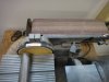
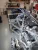
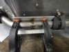
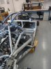
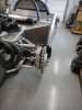
The coolant lines have now been tacked-up and are ready to go out for finish welding.
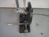
This was actually kind of a fun job. Using a chop saw and a belt sander helped it go more quickly. The chop saw made quick work of the cuts and the belt sander helped clean the ends after cutting. Various markers were used to identify the "clocking" position of each of the pipes where they joined together. This will also help the welder to keep things aligned if anything moves in his shop or in transit. It took about 10 hours to tack both sets of pipes, including setup and cleanup.
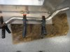
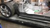
I wanted the new pipes to fit into the old clamps, so a fair bit of the time was taken up in clamping the pipes into position, removing them, tacking a weld and then repeating the process for the next piece in line. I cut up some spare strips of pipe insulation to temporarily hold the pipes centered in the clamps when fitting each piece. The final insulation should help provide some vibration and flex absorption when the car is running.
I found the side of the car made a handy place for tacking; the pipes could be clamped onto the flat surface and the straight sides helped keep the pipes in alignment. There are no electrics installed in the car yet, so no worries about damage from the MIG welder (not sure if this would have been a problem or not . . .)
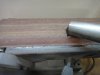
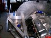
For each side, I started at the ends and worked towards the middle, which made each assembly a little smaller and easier to move around. When it came time to join the two assemblies together, a scrap piece of angle clamped onto the pipes helped hold them in alignment for welding.
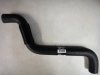
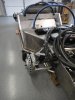
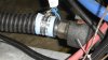
For the passenger side rear and drivers side front connections to the engine and radiator, respectively, a single Gates hose was used, cut in two. One piece provides a nice "S" around the fuel filler at the back of the car and the remaining piece bridges the gap between the front driver's pipe and the radiator. For the other two connections, I am re-using the stainless steel flex pipe that was previously used for both front connections. I was tempted to just weld the pipes and figure out the hose connections later. I'm glad I didn't do this, as finding the right shape for the "S" would have been a real pain, as opposed to just tacking the pipes into the right position once the "S" was already in place.
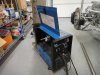
The tools used for this were:
- Chop Saw (e.g. 3-1/2 Horsepower 14 in. Industrial Cut-Off Saw)
- Belt Sander (e.g. Combination 4" x 36" Belt / 6" Disc Sander)
- Mig Welder (Millermatic Challenger 172) with stainless steel wire and Argon/C02 mix. I don't think this welder is available new any more. It's oversized for this kind of job as the pipe wall is only 16 gauge.
The pipes were all 304 Stainless 16 gauge, obtained from Columbia River Mandrel Bending http://www.mandrel-bends.com/catalog/ (thanks, Jack!) and included the following:
18 x 1.50" OD Straight Tube SS304-150-065
8 x 1.50" 2.25" Radius, 45 Degree Mandrel Bend SS304-16-150-225-045
3 x 1.50" 2.25" Radius, 90 Degree Mandrel Bend SS304-16-150-225-090
Total including shipping: $342.22
As it turned out, 4' less of the straight pipe would have been sufficient, but it's not expensive to add to the order and provided some comfort in the event of a re-do.
The hose is Gates part no. 22286. IIRC, it was $20 at the local autoparts store.
This was actually kind of a fun job. Using a chop saw and a belt sander helped it go more quickly. The chop saw made quick work of the cuts and the belt sander helped clean the ends after cutting. Various markers were used to identify the "clocking" position of each of the pipes where they joined together. This will also help the welder to keep things aligned if anything moves in his shop or in transit. It took about 10 hours to tack both sets of pipes, including setup and cleanup.
I wanted the new pipes to fit into the old clamps, so a fair bit of the time was taken up in clamping the pipes into position, removing them, tacking a weld and then repeating the process for the next piece in line. I cut up some spare strips of pipe insulation to temporarily hold the pipes centered in the clamps when fitting each piece. The final insulation should help provide some vibration and flex absorption when the car is running.
I found the side of the car made a handy place for tacking; the pipes could be clamped onto the flat surface and the straight sides helped keep the pipes in alignment. There are no electrics installed in the car yet, so no worries about damage from the MIG welder (not sure if this would have been a problem or not . . .)
For each side, I started at the ends and worked towards the middle, which made each assembly a little smaller and easier to move around. When it came time to join the two assemblies together, a scrap piece of angle clamped onto the pipes helped hold them in alignment for welding.
For the passenger side rear and drivers side front connections to the engine and radiator, respectively, a single Gates hose was used, cut in two. One piece provides a nice "S" around the fuel filler at the back of the car and the remaining piece bridges the gap between the front driver's pipe and the radiator. For the other two connections, I am re-using the stainless steel flex pipe that was previously used for both front connections. I was tempted to just weld the pipes and figure out the hose connections later. I'm glad I didn't do this, as finding the right shape for the "S" would have been a real pain, as opposed to just tacking the pipes into the right position once the "S" was already in place.
The tools used for this were:
- Chop Saw (e.g. 3-1/2 Horsepower 14 in. Industrial Cut-Off Saw)
- Belt Sander (e.g. Combination 4" x 36" Belt / 6" Disc Sander)
- Mig Welder (Millermatic Challenger 172) with stainless steel wire and Argon/C02 mix. I don't think this welder is available new any more. It's oversized for this kind of job as the pipe wall is only 16 gauge.
The pipes were all 304 Stainless 16 gauge, obtained from Columbia River Mandrel Bending http://www.mandrel-bends.com/catalog/ (thanks, Jack!) and included the following:
18 x 1.50" OD Straight Tube SS304-150-065
8 x 1.50" 2.25" Radius, 45 Degree Mandrel Bend SS304-16-150-225-045
3 x 1.50" 2.25" Radius, 90 Degree Mandrel Bend SS304-16-150-225-090
Total including shipping: $342.22
As it turned out, 4' less of the straight pipe would have been sufficient, but it's not expensive to add to the order and provided some comfort in the event of a re-do.
The hose is Gates part no. 22286. IIRC, it was $20 at the local autoparts store.
Attachments
-
 DSC05174.JPG82.7 KB · Views: 345
 -
 DSC05170.JPG106.1 KB · Views: 305
 -
 DSC05175.JPG88.3 KB · Views: 294
 -
 DSC05177.JPG53.9 KB · Views: 317
 -
 DSC05169.JPG76.4 KB · Views: 302
 -
 DSC05191.JPG121.5 KB · Views: 1,835
 -
 DSC05183.JPG91.2 KB · Views: 330
 -
 DSC05179.JPG74.1 KB · Views: 323
 -
 DSC05178.JPG75.7 KB · Views: 313
 -
 DSC05173.JPG90.9 KB · Views: 316
 -
 DSC05192.JPG105.3 KB · Views: 330
 -
 DSC05193.JPG95.8 KB · Views: 365
 -
 DSC05194.JPG94 KB · Views: 312
Last edited:
Is the run on the drivers side engine bulkhead typical? I am having mine finished out this weekend and I didn't follow that route to the water pump.
Howard Jones
Supporter
Mine went like this. Use as few 90s as possible, even 2 45s a couple of feet apart are better. I put a couple of 90 in mine where on reflection I could have done a 45 and then another 45 down stream in the nose. I sure it will be fine but the straighter everything is the better it will all work.
Attachments
Here are mine, I made them out of 1-1/2 copper, easy to work with and solder together. Fittings are easy to get, about 20 ft of copper I used on mine with a 20 B rotary, some elbows, 45 degrees, female adapters to barb fittings for the hose connections.
about 400.00 with the insulation.
about 400.00 with the insulation.
Attachments
I used hard copper line. It would kink before it would bend if you didnt heat it up. K pipe
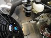
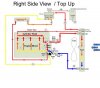
Further to the subject to cooling lines and routing: I am following the coolant scheme in the attached diagram, except that there does not appear to be a steam tube port on the radiator, so I am planning to simply "T" line 4 into line 14 in the engine compartment near the Pressure Bottle.
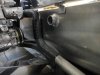
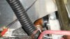
The Steam Tube coming off the LS7 engine appears to be 1/4" outside diameter. I'm thinking of making line 14 the same diameter using aluminum tubing, but am wondering if this is large enough, given the long run from the radiator at the front of the car to the "T" in the engine compartment.
What do you guys think?
Dave
Attachments
Ken Roberts
Supporter
That's the size of my line. I used 4AN stainless braided teflon hose (Aeroquip). It's not that expensive at that size.
Similar threads
- Replies
- 11
- Views
- 1K
- Replies
- 19
- Views
- 4K