Restarting my SLC project in West Texas

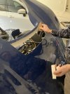
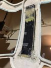
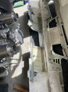
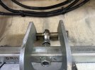
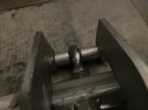
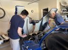
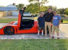
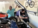
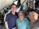
In July very cool visitors came to West Texas, Cam drove his SLC from Denver in 110 degree weather!!! What a friend. The SLC held up nicely and Cam did not melt. Howard also drove from New Braunfels for the SLC owners West Texas reunion LOL. How many guys does it take to finish a front hinge ???

It was amazing to see 2 SLCs in my garage. We had a great time !!! Ands lots of stories, Howard even played his guitar.
 

Attachments

  • 4376e4c8-e878-4112-bb22-d27dfbca8132.jpg
    4376e4c8-e878-4112-bb22-d27dfbca8132.jpg
    163.8 KB · Views: 216
  • IMG_5558.jpeg
    IMG_5558.jpeg
    453.7 KB · Views: 175
  • IMG_5576.jpeg
    IMG_5576.jpeg
    474.8 KB · Views: 118
  • IMG_5582.jpeg
    IMG_5582.jpeg
    439.3 KB · Views: 124
  • IMG_5560.jpeg
    IMG_5560.jpeg
    421.1 KB · Views: 147

Howard Jones

Supporter
Hector and his family are some of the nicest people you would ever have the privilege to meet. I hope to go back and see them again as soon as possible. Cam made an epic voyage in his SLC. I wonder if that isn't the longest to date? Approx 1500 miles found trip.
 
Last edited:
Hector and his family are some of the nicest people you would ever have the privilege to meet. I hope to go back and see them again. as soon as possible. Cam made an epic voyage in his SLC. I wonder if that isn't the longest to date? Approx 1500 miles found trip.
Thanks Howard, really enjoyed the visit, we have to do it again soon. And I am planning to break Cam's record for the longest SLC trip. without using a tow truck or a trailer. :)
 
Next found a way to mount the windshield wiper motor, decided to go the bonded aluminum plates to the fiberglass route .
 

Attachments

  • IMG_2480.jpeg
    IMG_2480.jpeg
    170.8 KB · Views: 89
  • IMG_2481.jpeg
    IMG_2481.jpeg
    204.5 KB · Views: 83
  • IMG_2483.jpeg
    IMG_2483.jpeg
    411.5 KB · Views: 98
A recess was made on one of the aluminum mounting plates using a router and a mounting screw was also attached to the same plate and holes for the mounting tabs on the other. I figure there will be a lot of torque on the mounting plates as the windshield wiper turns back and forth.
 

Attachments

  • IMG_3634.jpeg
    IMG_3634.jpeg
    414.4 KB · Views: 76
  • IMG_3633.jpeg
    IMG_3633.jpeg
    266.3 KB · Views: 74
  • IMG_3635.jpeg
    IMG_3635.jpeg
    346.2 KB · Views: 84
I am way behind on my updates, here is a little progress

I did a little research on trying to maximize cooling while minimizing drag, making a very long story short , you want inlet area to be around 60% of the radiator core and you want the outlet area to be around 120-130% of the inlet area, therefore the outlet on the front clam needs to be opened quite a bit. There is also an area in front of the radiator on top that needs to be blocked to avoid air stagnation and vortexes formation. Howard noticed a marked increased in cooling when he blocked that area off.

1. use insulation foam to close the area in front of the radiator, I will glue it to the front clam later after the headlight harness is installed
 

Attachments

  • IMG_2507.jpeg
    IMG_2507.jpeg
    269 KB · Views: 39
2. Manufacture the intake duct. I chose to reverse the shield that came with the kit, never understood the original design. the fans push the air at close to a 90 degree angle , creating a massive amount of turbulent and reverse flow.
had to have room on one side for the fluid reservoirs and the a/c parts on the other.
 

Attachments

  • IMG_2489.jpeg
    IMG_2489.jpeg
    263.8 KB · Views: 38
  • IMG_2493.jpeg
    IMG_2493.jpeg
    243.4 KB · Views: 33
  • IMG_2506.jpeg
    IMG_2506.jpeg
    317.8 KB · Views: 32
  • IMG_2558.jpeg
    IMG_2558.jpeg
    255.1 KB · Views: 30
  • IMG_2563.jpeg
    IMG_2563.jpeg
    293.8 KB · Views: 31
  • IMG_2568.jpeg
    IMG_2568.jpeg
    212.9 KB · Views: 37
Decided to create some air foils, to better direct flow and also to block the view into the duct

The air foils were curved on two different planes , I should have done straight foils like Allan does, but decided to get fancy, I believe that was a mistake, very difficult to accomplish with rudimentary tools and modeling clay, it is very difficult to Lay the fiberglass perfectly on a foil shape. the end results were cosmetically challenged but functionally acceptable.

Also added a little insulation to the duct surface
 

Attachments

  • IMG_2543.jpeg
    IMG_2543.jpeg
    183.4 KB · Views: 37
  • IMG_2547.jpeg
    IMG_2547.jpeg
    426.1 KB · Views: 35
  • IMG_3602.jpeg
    IMG_3602.jpeg
    297.6 KB · Views: 35
  • IMG_3599.jpeg
    IMG_3599.jpeg
    258 KB · Views: 39
  • IMG_3606.jpeg
    IMG_3606.jpeg
    310.7 KB · Views: 40
Last edited:
Also had to add an air foil the the rear surface of the opening I made so that the air would not hit a flat surface at a 90 degree angle
 

Attachments

  • IMG_2554.jpeg
    IMG_2554.jpeg
    368.7 KB · Views: 38
  • IMG_2551.jpeg
    IMG_2551.jpeg
    217.2 KB · Views: 36
  • IMG_2555.jpeg
    IMG_2555.jpeg
    123.5 KB · Views: 35
  • IMG_3563.jpeg
    IMG_3563.jpeg
    284.9 KB · Views: 39
And here is the final product, again, cosmetically challenged but functionally acceptable .I tried to have the air foils follow the opening curvature, which was not easy at all. I am not too happy with the air foils so the opening will be covered with black wire mesh. Of note, the original opening remains intact and functional , so now there are 2 outlet openings . the outlet area is about 130% of the inlet area .
 

Attachments

  • IMG_3605 2.jpeg
    IMG_3605 2.jpeg
    289.9 KB · Views: 57
I am way behind on my posts , I will try to catch up a little

Next was the roof scoop duct, to direct air from the front scoop to the engine compartment , it also prevents water and debris from entering the cabin. Tricky to make for sure as it has to follow the roof curvature, fit between the roll cage bars , clear the small opening between the firewall and the roof and wider dimension at the front to cover the entire front scoop. Truly a fiberglass challenge.

I made the contour cutting some old foam pieces to follow the cage tubes, made myself a little wiggle room so that the duct will fit between the parallel roll cage bars. Used very thin sheet metal to form the floor of the duct.

I decided to bond it while the spider was hanging from the roof since I don't have my son Miguel anymore to help me flip the spider upside down. another challenge, glassing it in place upside down. But got it done.

I used a little bondo on the inside to keep all the surfaces smooth.

Finally painted the inside surface black so that it would not be visible through the front scoop.
 

Attachments

  • IMG_3541.jpeg
    IMG_3541.jpeg
    284.5 KB · Views: 30
  • IMG_3540.jpeg
    IMG_3540.jpeg
    409 KB · Views: 29
  • IMG_3545.jpeg
    IMG_3545.jpeg
    267.3 KB · Views: 29
  • IMG_3647.jpeg
    IMG_3647.jpeg
    499.5 KB · Views: 29
  • IMG_3659.jpeg
    IMG_3659.jpeg
    255.2 KB · Views: 31
  • IMG_3663.jpeg
    IMG_3663.jpeg
    300 KB · Views: 50
I cut a hole on the rear clam for the clam to clear the transmission when fully opened , that meant the rear hinge had to be split in half and therefore the clam reinforced with extra layers of cloth fiberglass and an additional aluminum square tube. Hopefully it will hold .

After the spider was centered, then the rear clam was centered as well, aluminum spacers were made to keep the rear clam at the perfect position relative to the tires.
 

Attachments

  • IMG_1783.jpeg
    IMG_1783.jpeg
    304.2 KB · Views: 33
  • IMG_2777.jpeg
    IMG_2777.jpeg
    384.4 KB · Views: 34
  • IMG_2787 2.jpeg
    IMG_2787 2.jpeg
    282.8 KB · Views: 32
  • IMG_2789.jpeg
    IMG_2789.jpeg
    217.8 KB · Views: 38
Next was the rear clam window and vents, the vents were straight forward , I ordered the standard ones, the finish looks standard but they are made from carbon fiber anyway, I'll take it, they are super light.

I was very nervous about cutting the plexiglass, as everybody knows getting spare parts takes forever, so I made a very detailed cardboard mockup , which was not easy due to the curvature.

At the end turned out really good, I won't take the protective plastic off for a while .

I used flat head recessed screws and JB welded weld nuts.
 

Attachments

  • IMG_1517.jpeg
    IMG_1517.jpeg
    222.3 KB · Views: 18
  • IMG_1510.jpeg
    IMG_1510.jpeg
    317.7 KB · Views: 17
  • IMG_1509.jpeg
    IMG_1509.jpeg
    278.1 KB · Views: 18
I just looked at the beginning of this thread, was started on May 19th, 2020. So I need to have the car at a a 98% or better finish by May 19th 2024, (meaning a few cosmetic details left, of course the car will never be 100% , right? ), and for sure must be driving on the street by then. So there, a firm commitment from me, my wife will be happy LOL .

It also means I have to hurry up and catch up on my posts as well.

4 years, Wow!! That is a long time. Thank you all for your support, this project would have been impossible without the awesome members of this forum. Cheers!!! Built not bought !!!
 

Mark B.

Supporter
You're doing a lot better than I did, Hector! Got my kit Feb 2014, street legal Oct 2021, painted April 2024. Great craftsmanship as usual -- it's looking fantastic so far!
 
Next was the rear clam window and vents, the vents were straight forward , I ordered the standard ones, the finish looks standard but they are made from carbon fiber anyway, I'll take it, they are super light.

I was very nervous about cutting the plexiglass, as everybody knows getting spare parts takes forever, so I made a very detailed cardboard mockup , which was not easy due to the curvature.

At the end turned out really good, I won't take the protective plastic off for a while .

I used flat head recessed screws and JB welded weld nuts.

FWIW, the directions from Shields (who is/was the manufacturer of the parts) says not to counter-sink the holes .... I've always thought the trick to avoiding cracks in the plastic is a slightly over-sized hole and then cushion the bolt head with a rubber washer .... that's how I did my windshield using 4 #6s and it's been fine for 15 years. YMMV.
 
Back
Top