Scotts build thread

I would think about placing the NACA inlet duct for the front brakes right at the narrow point in the horizontal front bodywork along side the tire surround. This area has a natural high pressure area due to the compression effect of the airflow and solves two different things. One, provides a escape for that high pressure zone thus possibly reducing drag somewhat and two, uses the pressurized air to cool the brakes. The ducting will be a bit more complicated than the headlight surround side but hell you can handle that.

The other idea I had was using the area of the bat wings to capture inlet air for the brakes. They would need to be made thicker but if all you need is the area of a 3 inch hose, about 7 sq inches, it could be something like 1 1/2 inch thick with a 1 inch slot across front 7 or 8 inch's wide. Duct it out the side of the batwing into the fender enclosure, adapt the duct to 3 inch diameter inside the fender and to the brakes via hose.

Another two fer. Downforce from the batwing and brake cooling inlet duct all in one.

Hey Howard. I have a couple run of the mill naca ducts here I have been trying, but a 3" exit one is just too big to fit with the standard design.
The possibility of making the winglet itself somehow part of it, I havn't yet explored. Will give it some thought.
 
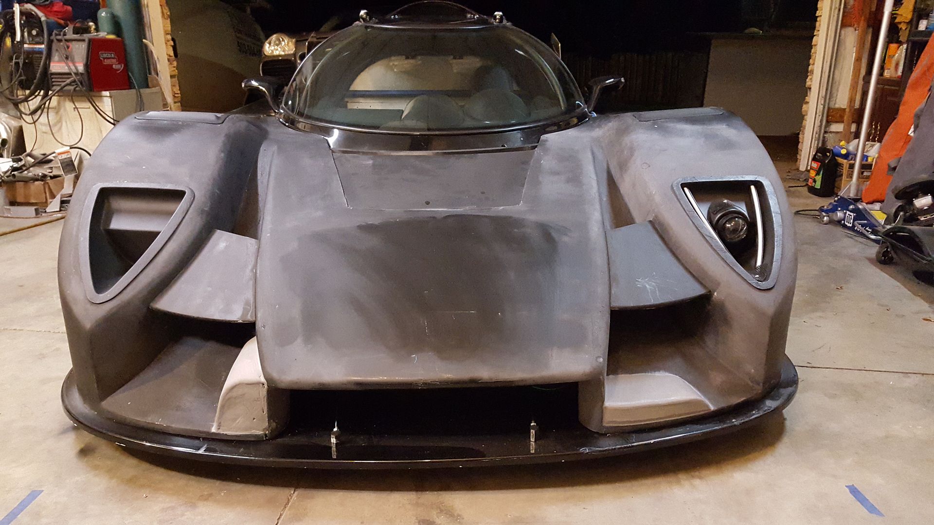
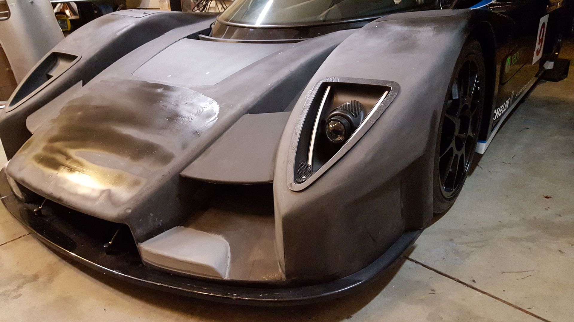
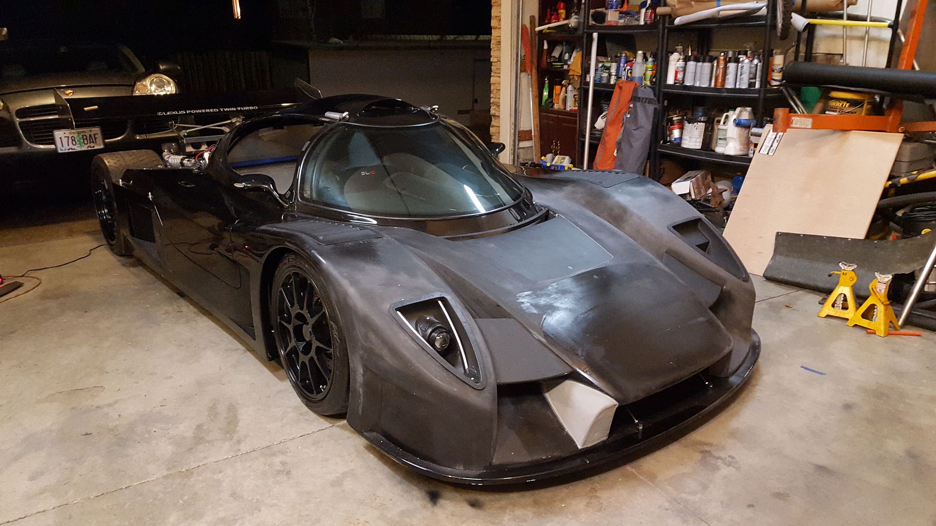
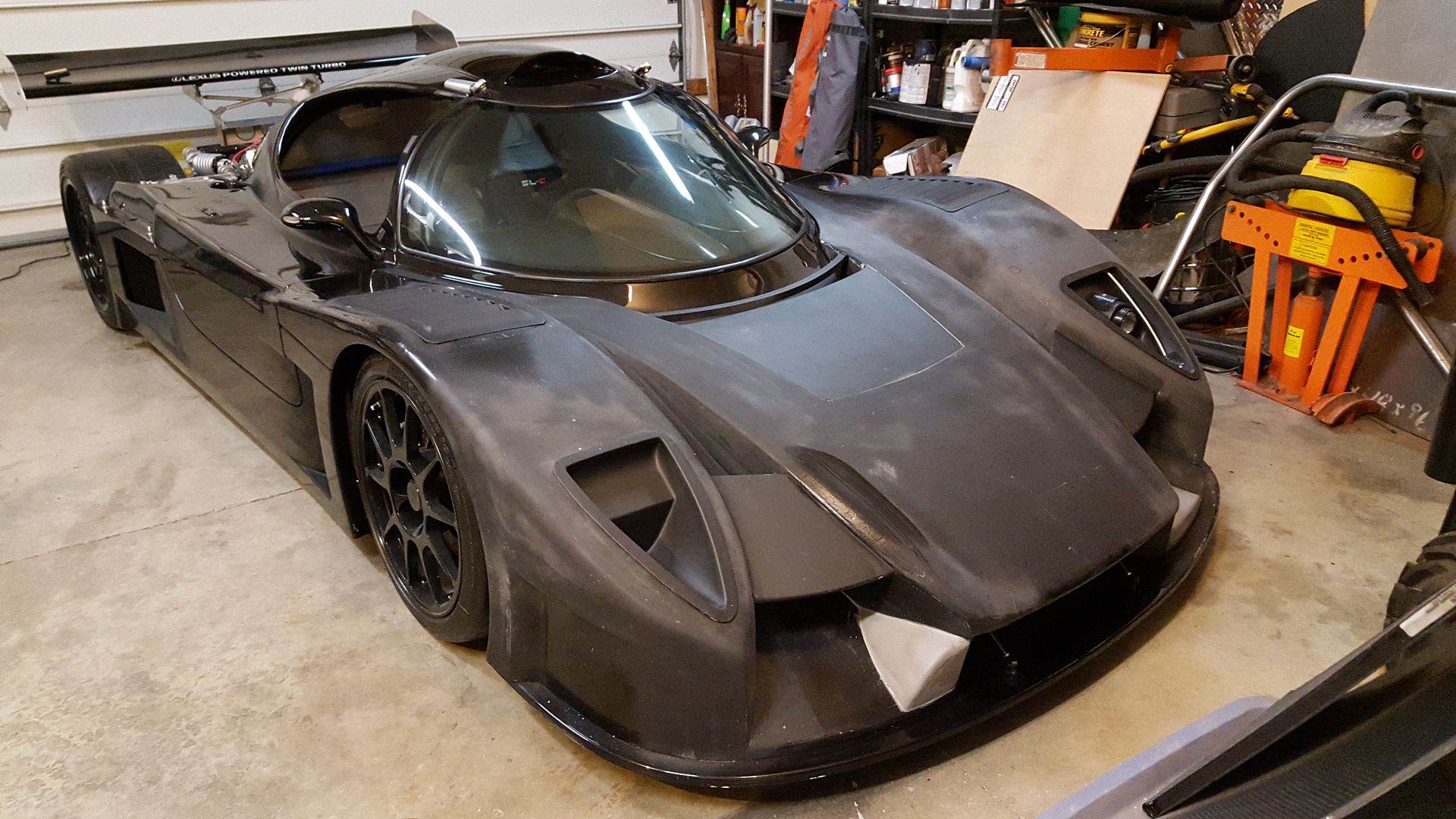
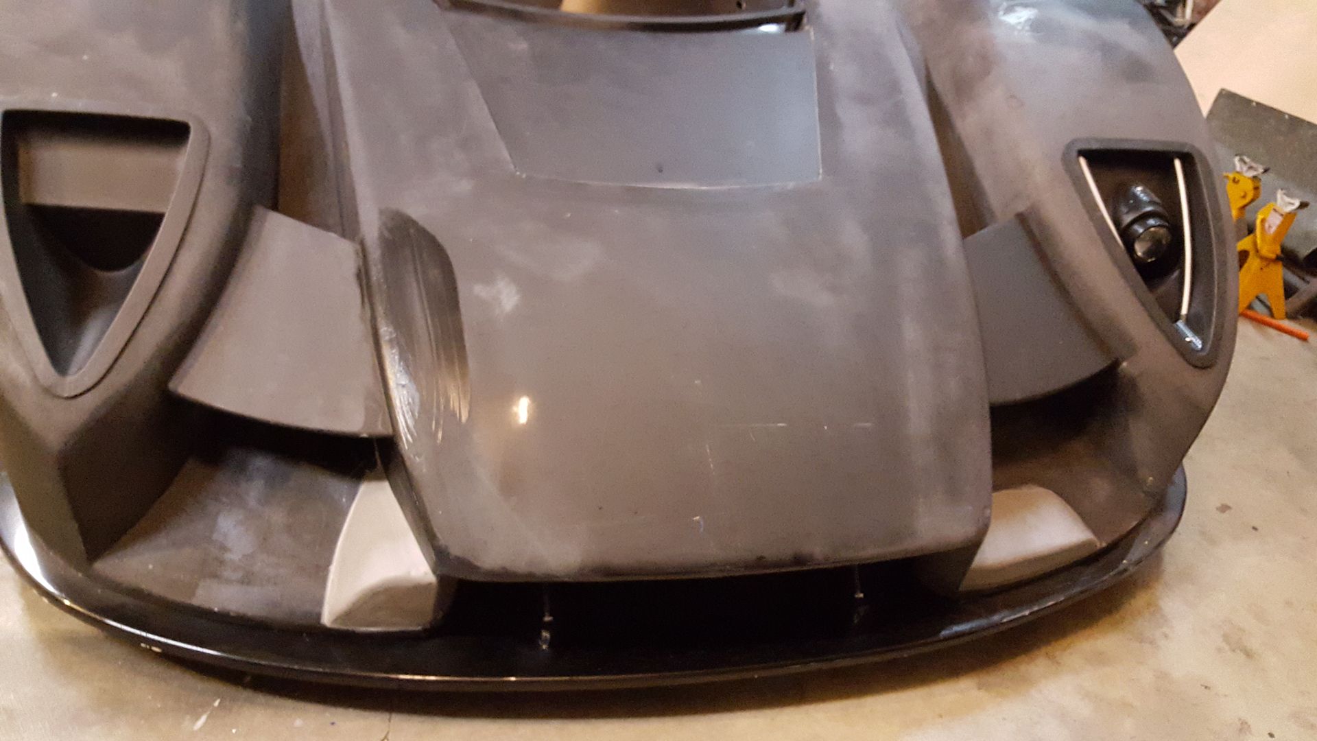
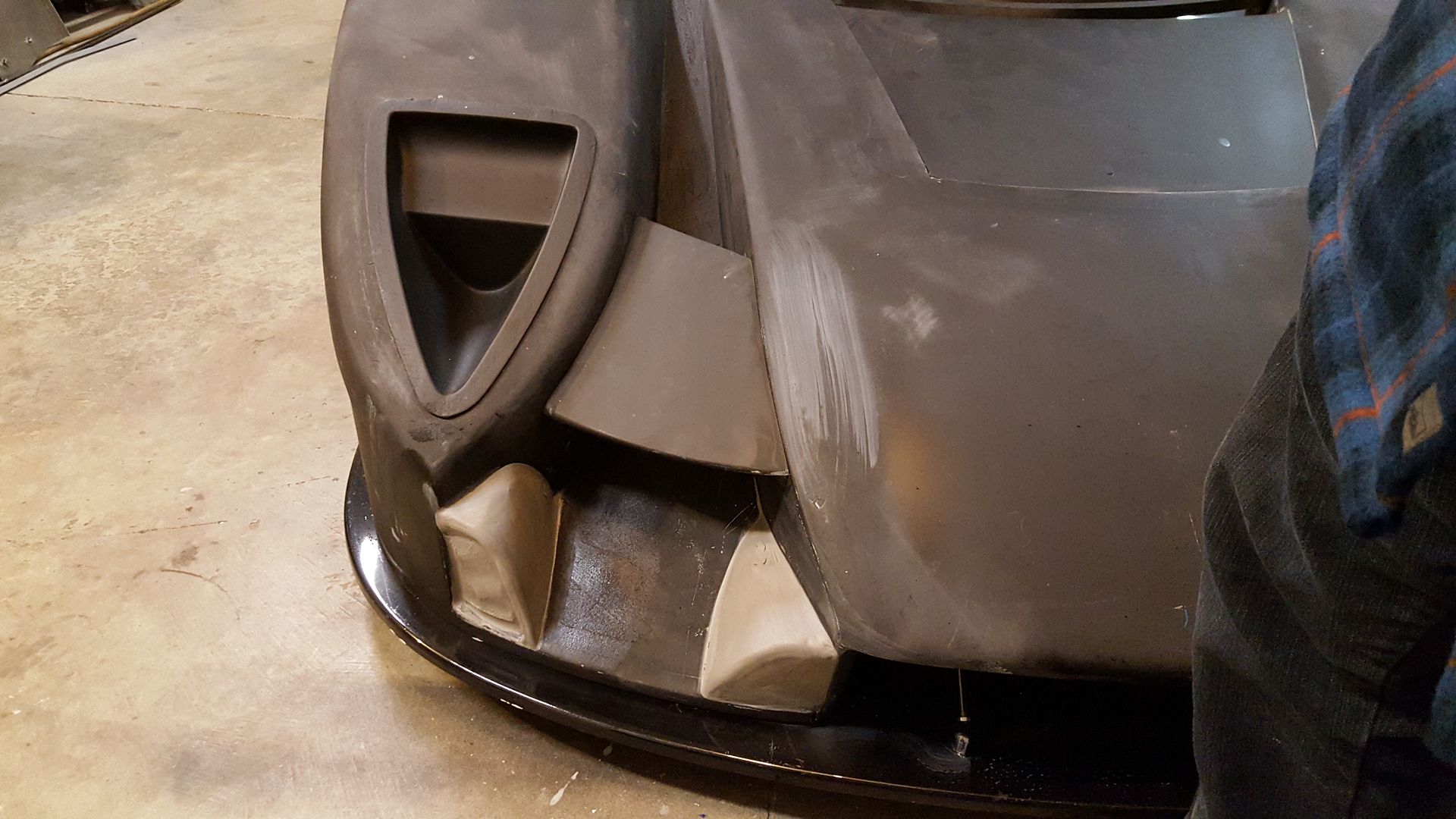
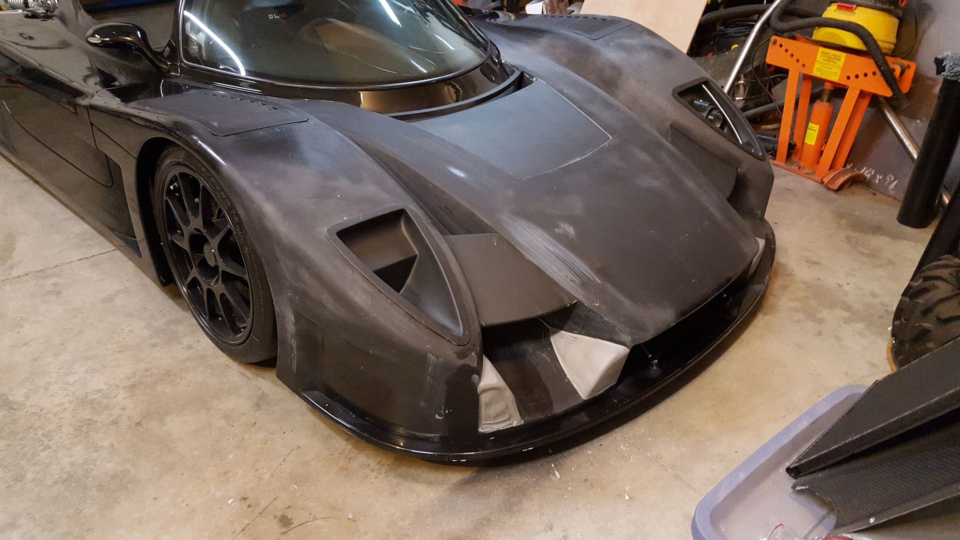
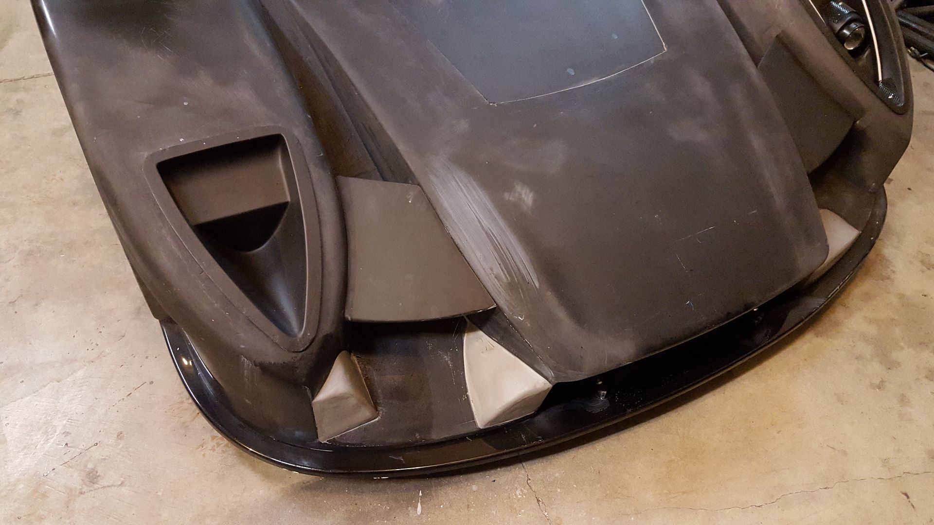
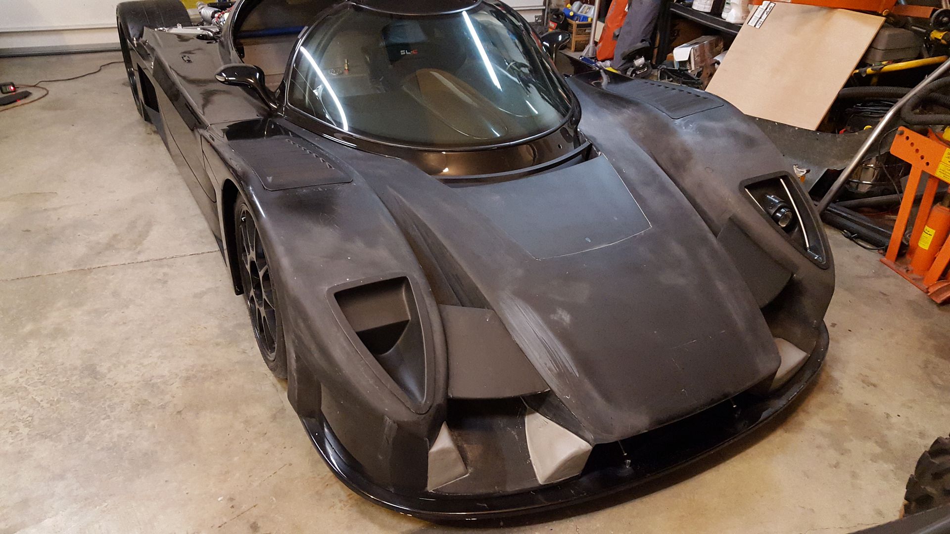
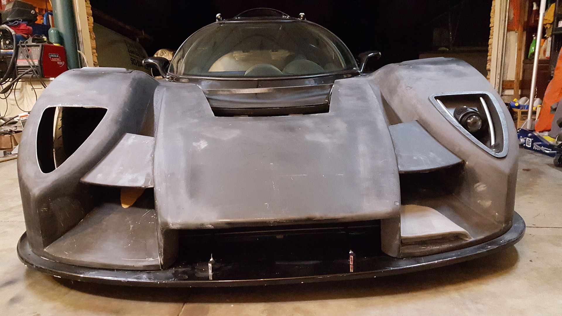
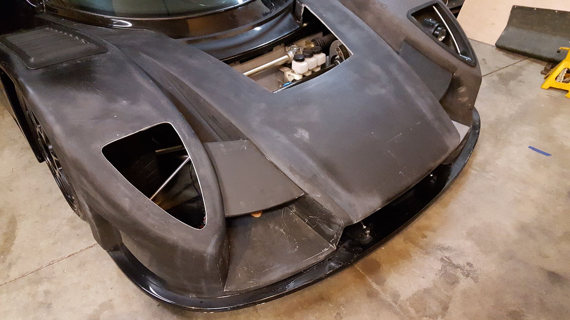
Had a little spare time, so figured I would mock up a couple brake duct designs. Not super sure on either of these. Maybe the drivers side one would work if smoothed out further.


Larry L.

Lifetime Supporter
Is there any reason (e.g.: not enough space around the wheel/tire/front suspension pieces to allow for turning, etc....'bulkhead/'chassis' in the way...no way to run the duct hose from there...whatever) that you can't cut an opening for the brake duct intakes right down at the very bottom of, and on the inboard side of the 'pointy end'(!)/leading edge of the front 'fenders'?

That way they wouldn't stick out into the 'channel' between the fenders and the radiator/nose area and the air flow wouldn't be affected/disrupted at all.

If the above is clear as mud and you'd like to know what the devil I'm talking about, lemme know and I'll 'p.m.' my phone number!

THAT CAR IS LOOKING NASTIER BY THE DAY!!!
 
I understand exactly what you are talking about. I havn't made anything on that side because I really like that point to be defined. I think it is worth a shot though.
 

Larry L.

Lifetime Supporter
"X" number of thin "horizontal" slats across the duct opening should maintain said definition, don't ya think? :shrug:
 
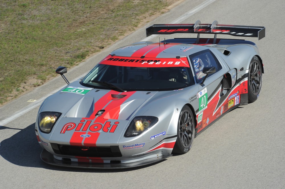
The Robertson Ford GTR ran two one inch tall by four inch wide slots to cool their much larger brakes for Le Mans. Picking a high pressure area is part of the key.
Remember you can over cool rotors , hence the mk2 gt40 pulling air from behind the radiator to prevent such dramatic thermal shock cracking brake rotors
 
What about placing the duct on the outside of the fender back towards the wheel opening? I am not sure if you plan on using canards or not.

But where the step is, would be just inside of the inner fender and you could route the brake duct from there.

Another option is if you could find away to work a duct off the back edge of your headlights. The only issue with this right now, is your headlight are not flush with with the body work.
9k=
9k=
 
I like the inside pod more for a fog light mount than for a brake duct. Make it longer, with a little more shape.
 
Last edited:
The Robertson Ford GTR ran two one inch tall by four inch wide slots to cool their much larger brakes for Le Mans. Picking a high pressure area is part of the key.
Remember you can over cool rotors , hence the mk2 gt40 pulling air from behind the radiator to prevent such dramatic thermal shock cracking brake rotors

I found a pic of it. I am guessing you are talking about the two slots right where it meets the splitter.

robertson-racing-doran-ford-gt-r-robertson-20733.jpg


I could make the ducts pull from inside of the front of the rad box, it should pressurize a bit with both the a/c condenser, and radiator. I have always had that as my back burner routing method if all else fails.
I think the drivers side mock up one might be the design to pursue a little further at least. It would have roughly a 9"x1.25" opening, and be the easiest to mold. I only have the street splitter, they would become a bit more effective with bigger splitter.
 
Rather than add blisters to the smooth lines you created in the front, why not run a NACA duct? It will be flush and less noticeable. Run them on the inner side underneath those winglets.
 
Scott

The build looks fantastic. Never realized how complex aerodynamics could be. I have a simple question (I think), how are you making your forming bucks so quickly? You modeling with foam?

Thanks
 
Rather than add blisters to the smooth lines you created in the front, why not run a NACA duct? It will be flush and less noticeable. Run them on the inner side underneath those winglets.


That is another kind of back up plan. I am worried that once painted, the outline of the naca duct will look a little out of place. It will hide a little from certain angles, but be very visible from others. I think it would come off as a failed attempt to hide it when finished. Just exploring all options first.
 
Scott

The build looks fantastic. Never realized how complex aerodynamics could be. I have a simple question (I think), how are you making your forming bucks so quickly? You modeling with foam?

Thanks

I have started looking at the aero differently the last few months. Because of wind tunnel testing, we kind of get programmed to think the air is moving, when in reality, it is the air minding it's own business, and the car is moving. I really changes quite a few things when viewed in that arrangement.

The brake duct pieces are just solid clay, so they are very quick to make. Other stuff, I just look around the garage to piece something together or mold off of other parts of the car to get specific shapes. Just need to be a little creative. :thumbsup:
 

Howard Jones

Supporter
P Roth and I are saying the same thing. Below the "bat wings" and slightly forward of their leading edge would be my choice for a NACA duct. Then run the exhaust from the duct inside the inboard side of wheel well along side the lights.

This spot is in a pretty high pressure area. You might be able to use 2 1/2 inch outlet NACA duct. The smaller size will avoid a big duct inside the wheel well. Work out the area of a 2.5 inch hose and size the ductwork just a bit larger in area. The neck it down to the hose size farther back in the wheel well. Attach the hose to the inside panel and mate it up with the ducting with a fixture so that the hose can stay with the chassis when you remove the nose bodywork.
 
I made a cut out of a small 2.5" naca duct, and started toying with it. Alot smaller than I thought it would be. Then, decided to cut a little off the front of the naca duct opening, and it really almost disappears under the bat wing thing.
I think a little more work needs to happen around the rad opening though. Something has been kinda bugging me, and I think i finally figured it out.
Howard, that is exactly how the ducts will be run. Already have all the connectors for it too.


Howard Jones

Supporter
Here is pretty much what I was thinking. Either on the top of the ramp like these or in the vertical inboard side of the fender enclosure. From Mulsanne's corner website.
 

Attachments

  • LolaB0540-6.jpg
    LolaB0540-6.jpg
    52.8 KB · Views: 296
  • LolaB0540-4.jpg
    LolaB0540-4.jpg
    42.3 KB · Views: 273
  • LolaB0540-BC1.jpg
    LolaB0540-BC1.jpg
    50.3 KB · Views: 296
My 2 cents, which is actually worth less than half that, is that the various mock ups are kind of visually disruptive. I know aerodynamics causes some weird looking designs sometimes, but aside from these latest additions, what you have done has remained visually nice.

In that line of thinking, either the NACA ducts under the winglets or just routing from the inside of the radiator opening under the bodywork would look the nicest.

Maybe that thought would change once they are created and painted to match the body, but as they are now they look a bit odd.

EDIT: had another thought - what about just using the existing leading edge of the bodywork between the radiator opening and the pontoon fronts? Might have to increase the height of it a little bit, but the point being it'd still be flat on the top and the same all the way across. Possibly only a portion of it could be opened for the ducts and the rest left solid, kind of like the Robertson car.
 
Last edited:
Back
Top