Scotts build thread

Are you planning to affix some sort of S.S. 'fine mesh' on the underside of same to prevent small stones (and whatever other debris) from blasting up thru 'em and saying 'Hello' to the car's paint?

I personally will put some mesh on inside as i will primarily be on the street and the paint job I am envisioning now, will be horrendously intricate.
 
3d solidworks or any other file type you have iges/stp would work.
Has to be an accurate model to give accurate results though obviously.

If your mods are purely aesthetic for you then don't sweat it but then also lets not presume it's going to be 100%. or better than the original starting point.

Enjoy

Ok. One of my car group buddies works for a company that writes this type of flow software, and he is trying to get me on as a beta tester for it. I have one of their really nice 3d programs now, but my inexperience in the program, or most things that happen on a dam computer, I have since only made a cylinder with a beveled edge in an hour. Hahaha. Scanning would have to be my option as yes, totally agree any variation from actual will show drastically different numbers. That worries me since part of it crests the top of fender, which puts different parts of the piece in vastly different airflows if not modeled perfectly. Because of it's location, I would really predict flow characteristics to transition back and forth between the two variants. One better at one speed, other better at another speed.

If this has come off as any type of competition or anything, that is exactly opposite of what I was trying to achieve. Numbers that I use, I only use as baseline numbers (to gauge my own ratios) and not meant as a competitive comparison. Purely just building my own car to reflect my tastes and the fact I have SERIOUS automotive OCD and can leave nothing untouched. Lol. My build motive really has been a balance between astetics, and function (what I feel will work atleast), with never trying to let one vastly outweigh the other. So anything i leave on the table design wise aimed at strict performance, was done to create the correct astetics.

I would really like to bring the whole front and rear package to you if I could catch you guys on a practice day. The front should set right on, and will keep in mind retrofit parameters on the rear while building it. Many months away, but keep in mind if interested.
If it works, it works. If it doesn't, I will hit the drawing board again, no biggy. I will just keep going here, so I do appreciate the feedback and participation recently in the process.
 
This helps relieve the pressure infront of the leading edge of the tyre , this is the highest pressure point, if you look at any aero trace the highest concentration of pressure around the wheels is where the tyre meets the road...also the hardest to alleviate...

The "hole" location/size is very carefully restricted by the rules guys...

If I have your meaning correct you are saying the tire is "aeroplaning" as compared to aquaplaning in relation to the road surface. Never thought of that.

Sorry Scott for the sidetrack.
 
I have always wondered if it was a factor they could ever simulate to see the actual effects. A guy could try putting a polyurethane brush in front of tire. Might atleast break up or disrupt/divert it a bit. Swap out at tire changes due to wear.
 

Larry L.

Lifetime Supporter
Hmmmm. This whole fender vent/air pressure/turbine discussion has gotten me to wondering if grafting similar vents to the f.f.s of a GT40 (MKI or II) would reduce or eliminate the tendency for a GT40's nose to 'lift' at speed?

Apologies for the sidetrack, Scott...
 
No probs Larry.

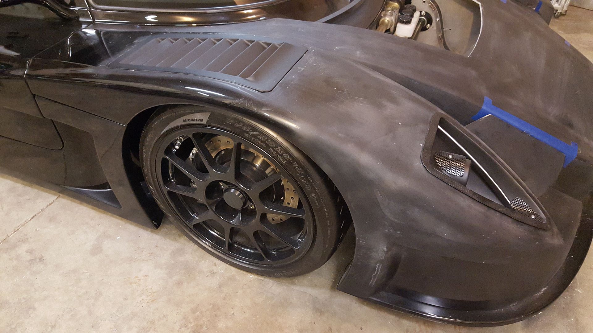
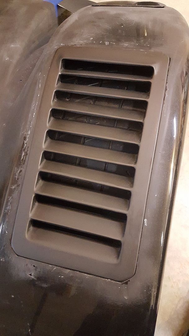
Here is the finished piece. Spent most of one day finishing this thing. Little files, etc, to get into all the crevices. Now for the other one!
I sat on them to test strength. It's still there. ;)


All parts to this point have been finished to about 80-90%. Waiting to get entire front end finished, then pull out gun and hit it with a super thick poly primer (basically sprayable bondo) to get perfect.
 
Last edited:
Sweet!
You my friend are a wildman. Do you ever sleep? :stunned:

Taking time off right now, so I put in 9am-5pm in the garage, then get my second wind about 8-9pm until 11pm. Lol.
Back to work next monday for two-three weeks, then taking off again until late january or early feb. Going to be seriously jonesing while out of town and not being able to work on it during week nights. Trying to get front end done before leaving. Still have brake ducts and the rad air exit to do still (plus the other fender vent) before monday. Bet it won't happen. Lol
 
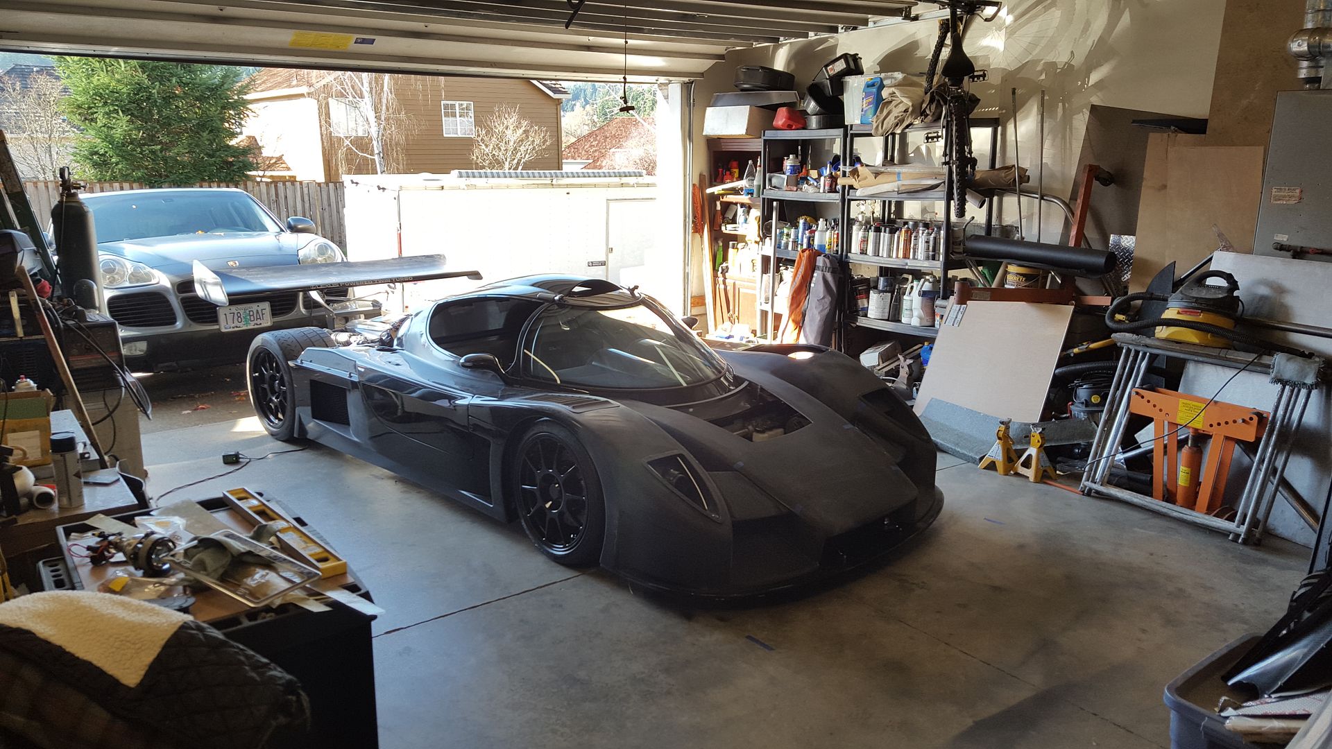
Wish my driveway wasn't so dam steep and I could roll this thing out all the way and actually get a good look at it.
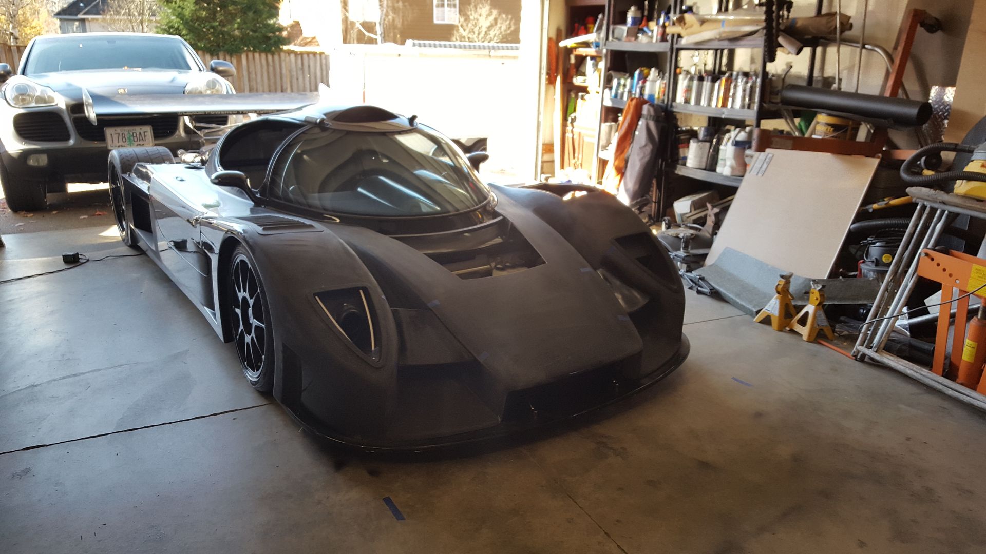
Not coming out too bad! Has a good look to it.


Keith

Moderator
Scott I have absolutely no idea if that works aerodynamically but it looks the bees knees (quaint English saying), so a tip of my hat in your direction sir.

Now then, have you had a teensie weensie thought about the shape of the front grill opening? Such a front end treatment as you have magnificently engineered possibly deserves an equally elegant 'mouth' solution yes? :lipsrsealed:

Yaknow, it does hint towards a big mouth bass if just looking at just the opening. Lol. I did make returns on the inside of it, but not much can be done given the radiator size and amount of air I want to go in.
I still have to figure the brake ducts, and one of the variations I have been tossing around, will change the opening a little. I knew the brake duct openings and rad air exit would be the major hang ups design wise.
 

Larry L.

Lifetime Supporter
I still have to figure the brake ducts, and one of the variations I have been tossing around, will change the opening a little. I knew the brake duct openings and rad air exit would be the major hang ups design wise.

I've envisioned a slight 'design mod' (if you're interested) that should, IMHO, accomplish that w/o screwing up what you've done so far. 'Wish I had the 'pewter' skills/knowledge that would allow me to post a drawing of same...:veryangry:

Yeeeew gotta FAX number...or aren't you anywhere NEAR as much of a "Primitive Pete" as I? :undecided: :laugh:

P.M. if interested. 'The Boss' and I will be leaving in about 10 minutes to attend a Thanksgiving 'soiree', but, 'will be back home early this evening...
 
Sending pm. Would be interested to see the idea. I have come up with about 20 variations so far though, so don't be surprised if I have already gone there. Lol.
 
Seems like you could put a duct on the inside flank of your outboard pod - kind of under your winglet filler panels, that area is going to have plenty of air pressure.

Pretty cool the 'first prototype' is getting a second life and is actually looking more like the current prototypes. Beneficially, without the big headlight bulges that are the norm on WEC cars right now.

Nice vision and execution Scott. Makes me wanna go saw on my car some more LOL.
 
Last edited:

Howard Jones

Supporter
I would think about placing the NACA inlet duct for the front brakes right at the narrow point in the horizontal front bodywork along side the tire surround. This area has a natural high pressure area due to the compression effect of the airflow and solves two different things. One, provides a escape for that high pressure zone thus possibly reducing drag somewhat and two, uses the pressurized air to cool the brakes. The ducting will be a bit more complicated than the headlight surround side but hell you can handle that.

The other idea I had was using the area of the bat wings to capture inlet air for the brakes. They would need to be made thicker but if all you need is the area of a 3 inch hose, about 7 sq inches, it could be something like 1 1/2 inch thick with a 1 inch slot across front 7 or 8 inch's wide. Duct it out the side of the batwing into the fender enclosure, adapt the duct to 3 inch diameter inside the fender and to the brakes via hose.

Another two fer. Downforce from the batwing and brake cooling inlet duct all in one.
 
Seems like you could put a duct on the inside flank of your outboard pod - kind of under your winglet filler panels, that area is going to have plenty of air pressure.

Pretty cool the 'first prototype' is getting a second life and is actually looking more like the current prototypes. Beneficially, without the big headlight bulges that are the norm on WEC cars right now.

Nice vision and execution Scott. Makes me wanna go saw on my car some more LOL.

Thanks for the compliment.
I was thinking of that position for the brake duct, under the winglet. I am really worried about disrupting the airflow in that area though. The air under that wing is getting compressed by the narrowing channel, and then the under side of it is wing shaped, further trying to speed the air up.
I am taking off monday to work out of town for 2-3 weeks, and my plan is to try to get very fluid with the cfd programs and software with my bored out of my mind evenings with no car to work on. Lol.
Right now, the number 1 plan was to just make a really wide opening, maybe 1.5" high, across the entire front opening of the drop section. It should be very high pressure and not disrupt airflow going into that channel, but, it will decrease the amount of air in the channel, which will take a little of the down force away.
Another is to just put ducting in the front of the rad airbox itself, hidden within the opening. It should not make a difference in there.

BTW- I saw your bypass air flaps you did on your radiators. Good move! Not many people think that one out. Huge deal to relieve that extra pressure. Still need to rework my shroud, and make similar high pressure flaps.
 
Back
Top