Scratch build MK IV

Hey guys,

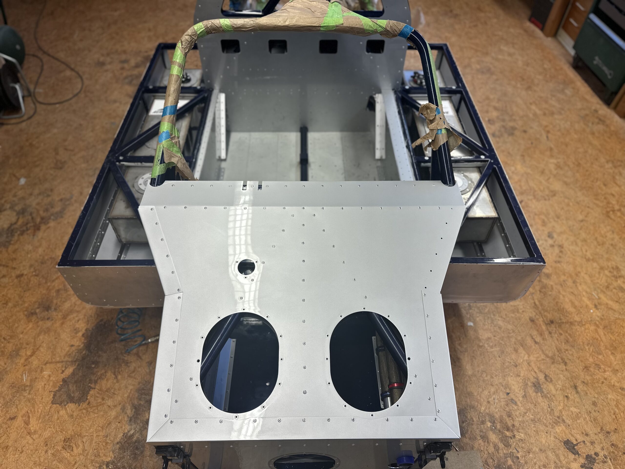
as many of you know, I have been working on my Ford GT40 MKIV for several years – a mix of original looks and modern technology. I have shared the whole journey, from the initial idea to sourcing parts and building the car, here in the forum time and again.

Since the project has now reached quite an advanced stage and I wanted to document my experiences in a structured way, I started a blog:

➡️ How my Ford GT40 MKIV Replica is made

There you will find a detailed chronicle of the project, technical background information and, of course, lots of pictures. I have set up the blog in two languages (German & English) so that as many interested people as possible can use it. Maybe some of you will find it interesting – feel free to take a look! I look forward to your feedback and discussions.

Best regards,
 

Attachments

  • IMG_2736.jpeg
    IMG_2736.jpeg
    541.4 KB · Views: 306
  • IMG_2737.jpeg
    IMG_2737.jpeg
    367.7 KB · Views: 315
  • IMG_2741.jpeg
    IMG_2741.jpeg
    314.2 KB · Views: 295
  • IMG_2742.jpeg
    IMG_2742.jpeg
    277.2 KB · Views: 294
Reason I ask is because the tanks on my AP build are designed to be linked as well, but I only have 1 bung in each tank. What fuel pump did you go with?
 
Take a look at my blog:
 
Hi all,
I’m currently plan my wiring on my Frame and I’m looking for ready-to-buy motorsport-grade ground distribution blocks / star points.
I don’t want to weld tabs or grind off powder coating on the chassis tubes — so I’m after bolt-on or stud-type solutions that can handle high current and are commonly used in motorsport.
If you know good products or suppliers (UK / EU preferred, but US is fine too), I’d really appreciate your recommendations.

Thanks,
Hans
 
I just bought these as main distribution terminals for my car. Using one for a power feed from the Alternator and into the loom and feed from the battery. They are very robust and mount with two screws. The stud is beefy.


I also looked at these but did not need all the distribution points and kept it simple for my application:

 
Hello everyone,
Can you perhaps tell me the dimensions of the triangular section on the left side of the Mark IV dashboard?
An approximate measurement is fine.
Thanks!
Dashboard.jpg
 
After a longer break from the forum, here’s a small progress update.


Over the last few months I’ve been wrestling with the wiring/electrical system of my car. Since I’m a complete beginner when it comes to electrics, I thought: “No big deal — these days there’s AI you can ask…” Well. I could write a whole novel about the nonsense ChatGPT told me along the way. In my opinion AI is pretty useless for technical development — unless you already know the subject really well. But then you don’t really need it in the first place. Anyway: I definitely learned a lot over the last months (even if it wasn’t exactly voluntary).


Initially I planned everything the classic way: relays, fuses, proper circuits. When that was done, it occurred to me that I could use the Cartek PDM/PDP system instead. A “proper” CAN/bus system was too expensive for me, and the learning curve felt way too steep. So: back to square one. Reading manuals, trying to understand what it all means, rethinking the whole concept… what can I say — I will never be a fan of electrics in this lifetime. I genuinely don’t understand how anyone can enjoy this stuff.


But anyway: by now all the wiring diagrams are finished, and I’ve ended up with almost 80 pages of documentation. So I can finally start building and implementing the first parts. Of course there’s always that underlying fear that something is still wrong. I did have an expert look over it — but if someone is just doing you a favor quickly, it’s easy for mistakes to remain hidden somewhere.


Next came the connector topic: I decided to use TE Deutsch connectors. Another… let’s call it “adventure.” They’re not always easy to get here in Germany, and just understanding TE’s naming/part-number system took quite some time. Plus I ordered a few wrong connectors — naturally the most expensive ones. I don’t even want to know how many hours I’ve spent on Mouser, TE and similar websites. Anyway, that’s history now.


This week I finally started assembling the first component. Behind the dashboard I have a box that acts as a central signal/distribution point. Everything coming from the PDP and the dashboard goes in and through there, and then out to the consumers. Lots of connectors, lots of pins — and everything is packaged very tightly.


On top of that I decided to build a star-type ground network with three distribution points: front, middle and rear. In hindsight that was probably… well… “ambitious.” Another idea I followed because of the AI, looking back. Now I have to route a few meters of heavy ground cable through the car. Three M8 welded studs on the chassis would probably have been the smarter solution. But you’re always smarter afterwards.


I 3D-printed the distribution box and the three ground distributors — at least that looks professional I’m also using a 5-way Littelfuse PDM.


Once my dashboard arrives in the next days, I can start laying all the harnesses into the car. And I’m pretty sure this is the first and last time I voluntarily do something this involved with electrics…
 

Attachments

  • SC_01.jpg
    SC_01.jpg
    110.1 KB · Views: 67
  • SC_02.jpg
    SC_02.jpg
    145.3 KB · Views: 71
  • SC_03.jpg
    SC_03.jpg
    149.1 KB · Views: 79
  • VBX_02.jpeg
    VBX_02.jpeg
    309.4 KB · Views: 86
  • VBX_04.jpeg
    VBX_04.jpeg
    352.5 KB · Views: 87
  • VBX_05.jpeg
    VBX_05.jpeg
    415.8 KB · Views: 91
Back
Top