Suspension help

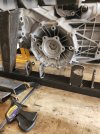
The UCA mounts look to be same height in this picture. If so, no anti-dive built in? The UCA on C5 has a visible upward angle with the front mount higher than the rear. I'm not a suspension theory expert, but by copying where the control arms were factory mounted on my homebuilt chassis, the resulting car handles like a dream. I did use C5 suspension both front and rear on my car.

I can see it's easier to mount UCA flat on that single chassis member but you might be better served by adding some angle to the UCA.
 

Kyle

GT40s Sponsor
Depends on the car. The c5 is 3200 lbs with 400+ sitting over the front end plus a higher CG. You don’t really need much antidive mechanically on the GT40
 
Thanks guys! I have seen so many ways to do this that I raised the back of the lower control arm and went with this. Not to worried about anti-dive since I will not be getting stupid with this. But thanks again for all the help. I'm sure I'll need more.
 
FFR did not incorporate any anti-dive into the GTM front suspension, horizontal UCA. Front end is light as discussed above. I did move my front UCA points on my GTM to recreate about 50% of the angle of the Corvette front UCA to bring some anti-dive back into the equation.
 
Ok folks here i go again. Got all the suspension mocked up and good. I put in some bracing in rear and noticed the angle bracing might not work so I picked up.my o1x and slid it into place. As I figured angle brace was hitting gear box so thathat won't work. But then I noticed on the left side the gearbox was hitting on the lca mount. Pic of it. Any suggestions. This is a custom build chassis
 

Attachments

  • 20260526_115427.jpg
    20260526_115427.jpg
    439.4 KB · Views: 56

Kyle

GT40s Sponsor
If it’s all custom then you can move anything to your hearts desire. You can try first to flip the uprights. Looks like your toe bar is in the rear.
 
Have you modelled the overall width of your intended wheel / tyre combination on those uprights and compared it to the actual rear clip opening?
You may be able to widen the track and angle the brackets outwards for a bit for extra clearance.

Clayton
 
Also suggest mocking up the position of the rear clamshell and seeing if you can or may need to move the drivetrain back to ensure the driveshafts are fairly close to the wheel centerline & wheel arch opening.
 
Have you modelled the overall width of your intended wheel / tyre combination on those uprights and compared it to the actual rear clip opening?
You may be able to widen the track and angle the brackets outwards for a bit for extra clearance.

Clayton
Unfortunately I have and that's as much as I can cheat it
I'm going to think on it for awhile. Might have to lower the lca mount some and cut off the top of the mount a little. Was just hoping for a better answer from some experienced guys. Thanks
4548.jpg
 

Ian Anderson

Lifetime Supporter
Thinking left field here
The transaxle…..can it be flipped.
To me it appears to have the input above the driveshafts with engine high.
Can it be flipped is engine is lowered and it may at the same time adjust the box position to fit the chassis.
 
Also suggest mocking up the position of the rear clamshell and seeing if you can or may need to move the drivetrain back to ensure the driveshafts are fairly close to the wheel centerline & wheel arch opening.
Hi Devin is it possible for you to measure the distance between your lower chassis where your lca mount and the tranny sits it would really help.me out thanks
 
Thinking left field here
The transaxle…..can it be flipped.
To me it appears to have the input above the driveshafts with engine high.
Can it be flipped is engine is lowered and it may at the same time adjust the box position to fit the chassis.
Can't flip since vent is on the top m of an o1x thanks though
 
Hi Devin is it possible for you to measure the distance between your lower chassis where your lca mount and the tranny sits it would really help.me out thanks
Alan, my LCA mounts are 17.3in center pivot to pivot and sit on top of my chassis rails which are 16in apart. This is about the maximum width I would make it using the C5 axles and getting the backspacing of wheels correct to fit under the wheelwells. If I were to do it again I would probably narrow the chassis rails to a minimum of 15in for the combination of parts I’m using.
IMG_1600.jpeg
 
New update on car. When I first did a test fit of the gearbox I was like....oh crap....it was hitting the frame members. I took last week off and walked away. Then contacted a fellow builder Devin and he gave me some advice and a measurement he used. Well I was worried that with his measurements I would not be able to get wheels from hitting body at the wheel wells. Thurs I thought, let me set up.the suspension and move the frame member out 2 inches then measure for wheel and backspace. Figured it would be ok since wheels are not dished. Friday I cut it apart moved both sides outboard and retacked it all. Then set gearbox back.in place and no hitting. On to welding and more frame members.
 

Attachments

  • 20260604_134018.jpg
    20260604_134018.jpg
    450.9 KB · Views: 10
  • 20260605_114921.jpg
    20260605_114921.jpg
    686.9 KB · Views: 10
  • 20260605_114908.jpg
    20260605_114908.jpg
    690.9 KB · Views: 10
Back
Top