Chuck and Ryan's RCR Build

An interesting thing to try might be to disconnect the tie rod and move it through the range to see how much camber gain is experienced and plot that line. Then reattach and check the bump steer. The only issue might be keeping the upright perfectly still without the tie rod attached as it was moved up and down.

As you mentioned, the effect of your method might be a toe out on compression which is a better result than going the other way. It is much more predictable under hard braking in a turn.
 

Chuck

Supporter
Dean:

Good thought, but you are right. Keeping the upright perfectly still would be a challenge. The slight toe in on bounce and toe out on jounce may actually be camber related, so it may be closer to neutral than the laser beam on the poster board would indicate.
 

Chuck

Supporter
Door stops revisited

Long ago we posted how we used a cable with a spring as a door stop. The cable had a compression fitting on one end and was then threaded through a small hole on the A pillar. And that was the problem. Threading it through that hole was a real pain once the dash was installed and the wiring in place. So an easy solution was found.

Starting with the same size cable as used before, stops were crimped eight inches apart on both ends. The outer diameter of the crimp is one quarter inch. The holes on the A pillar and door were then enlarged to just clear the crimp. On the A pillar, a half inch vertical slot was cut just wide enough to pass the cable so that the crimp could be held in place after passing through the hole. On the other end a once inch aluminum plate with a half inch slot holds the cable in place, with a spring to cushion the last couple of inches of door travel.

The cable stop can be easily removed and reinstalled. The cable is inconspicuous and the spring works well in cushioning the door when fully opened.
 

Attachments

  • DoorSpring1.JPG
    DoorSpring1.JPG
    333.1 KB · Views: 439
  • DoorSpring2.JPG
    DoorSpring2.JPG
    338.6 KB · Views: 444
  • DoorSpring3.JPG
    DoorSpring3.JPG
    315.3 KB · Views: 484

Chuck

Supporter
Cooling Fans

Long ago two cooling fans were added to the engine compartment. That is one of the most useful improvements made to our GT. In traffic the heat buildup in the engine compartment is substantial and if not addressed I suspect could eventually cause damage to the fiberglass. Heat soak after shut down leads to several issues.

As originally configured, the fans were activated manually with a dash switch that is wired independent of the ignition so that they can be left on after shut down to help cool the engine. With a year’s experience we have found that running the fans about ten minutes after shut down is sufficient to pull off the excess heat on a hot summer day. But sitting around waiting to shut off the fans after parking gets old, so a solution was sought.

An electronic time delayed relay, Waytex part number 75543, is an elegant solution. We mounted it under the dash to the right of the HVAC control panel. It is small and blends in well. Although the device is a 15 amp relay, the separate fan relay mounted in the rear near the fans was retained, permitting a 14 gauge wire to be used to connect the two rather than a heavier gauge. Note that the Waytex 12 volt power source (Connection #86) must be hot all the time.

The device has an adjustment on the rear so the shut off delay can be adjusted from zero to 10 minutes.

Two side by side Lucas SPST switches on the dash activate the cooling fans. One switch manually operates the front radiator fans, which are also activated by a coolant thermostat (on at 200 degrees, off at 180 degrees) and the AC compressor. The second switch activates the Waytex (wired to the negative terminal #85. Not the switched input, #87A, which is hard wired to the ignition). Once turned on the fan will remain on until the ignition is turned off, at which point it will remain on for the preset time. Since the activation switch is sourced from the ignition, it will shut off after the preset time once the engine is shut off even if the switch is left on. Since the dash switch cuts the ground effectively killing the power to the device, the fans can be manually shut off at any time.
 

Attachments

  • FanEngineRelay2.JPG
    FanEngineRelay2.JPG
    192 KB · Views: 453
  • FanEngineRelay3.JPG
    FanEngineRelay3.JPG
    366.3 KB · Views: 396
  • FanEngineRelay4.JPG
    FanEngineRelay4.JPG
    298 KB · Views: 413
  • DIAGRAMFANSWITCH.pdf
    276.8 KB · Views: 276
Dean:

Good thought, but you are right. Keeping the upright perfectly still would be a challenge. The slight toe in on bounce and toe out on jounce may actually be camber related, so it may be closer to neutral than the laser beam on the poster board would indicate.

Hi Chuck

If you fix the laser level 90° in relation to the brake rotor(clamp one a 90° angle and fix the laser to that, cardboard of course would be placed on the side of the car instead of front)) and using your same method to plot the laser track, you would eliminate the influence of camber and only plot the bump steer line ( as the planes of the two a arms are parallel, caster is not an issue, just make shure that your "zero line" is perpenticular to the a arms plane)

in your case changing the washers will not help, it will just change the balance ( less washers = more toe in bump in and less to out in bump out and vise versa with more washers). What you could do in your case is to move up the steering rack a bit, should be easy for you, because you have lowered it already, so take out one spacer and measure again, it should be improved if i´m not totaly wrong. But try to measure without the camber effect first. Send me a PM of your result and i can help you on that way

TOM
 
Last edited:
Chuck,
Glad to see you using the Waytex relay. I have wanted to have better control of my fans through the Waytex, but was unsure of how to accomplish it. Mine is wired such that the switch once tripped will stay on til the ignition is cut, regardless of the switch position, like yours. I have wanted to be able to turn the fans off once up to speed but haven't been able to do that. It is a power drain, or at least a strain on the alternator for them to continue to run when not needed. I will have to rewire mine as you have. Thanks for pointing that out.

Bill
 

Chuck

Supporter
Hi Chuck

If you fix the laser level 90° in relation to the brake rotor(clamp one a 90° angle and fix the laser to that, cardboard of course would be placed on the side of the car instead of front)) and using your same method to plot the laser track, you would eliminate the influence of camber and only plot the bump steer line ( as the planes of the two a arms are parallel, caster is not an issue, just make shure that your "zero line" is perpenticular to the a arms plane)

TOM

Tom: Good point. Placing the laser pointer at 90 degrees would indeed eliminate the variation caused by camber. But one would have to make sure that the reference line on the poster board was exactly parallel to the front upright, which given the presence of camber would be a bit of a challenge.

From a driving perspective we have no issues with bump steer. The GT does great on the road. If one factors the camber out of the diagram previously posted I suspect the bump steer would be measure quite close to neutral. Of course it would probably take a bit more than a carpenters level to confirm that with certainty.

Thanks for your insight. Good analysis, as usual.
 

Chuck

Supporter
Chuck,
Glad to see you using the Waytex relay. I have wanted to have better control of my fans through the Waytex, but was unsure of how to accomplish it. Mine is wired such that the switch once tripped will stay on til the ignition is cut, regardless of the switch position, like yours. I have wanted to be able to turn the fans off once up to speed but haven't been able to do that. It is a power drain, or at least a strain on the alternator for them to continue to run when not needed. I will have to rewire mine as you have. Thanks for pointing that out.

Bill

Your description of how your switch is functioning is exactly the way mine was wired previously. The trick is to not follow Waytek's diagram which shows a switch, wire that connection always on, and then switch the ground. That enables one to turn it off any time, yet permit it to run after the ignition is shut off for the pre set time when left on. Just switching a couple of wires on your set up will probably accomplish that goal.

Hope the diagram helps.

Chuck


Bill: I just read my post and it sounds like absolute gibberish. Hope you get the drift.
 
Tom: Good point. Placing the laser pointer at 90 degrees would indeed eliminate the variation caused by camber. But one would have to make sure that the reference line on the poster board was exactly parallel to the front upright, which given the presence of camber would be a bit of a challenge.

From a driving perspective we have no issues with bump steer. The GT does great on the road. If one factors the camber out of the diagram previously posted I suspect the bump steer would be measure quite close to neutral. Of course it would probably take a bit more than a carpenters level to confirm that with certainty.

Thanks for your insight. Good analysis, as usual.

Hi CHuck

THe camber would only stretch the line verticaly, there will be no horizontal diviation caused by the camber ( only by bump steer effects).THe movement of the upright is a function of the a-arm planes. As said the both a arms are in parallel plains to each other and in the same plane as the cars floor so any point mounted on the upright would have only a exact 90° ( perpenticular) movement to the a arm plane, when viewed from the side. Don´t mix up the caster. Caster only has effect in driving by developing a force to counteract steering and straighten the car. However it does not influence the geometry of the reference and plot line. Just put the car on stands so that the floor is in perfect level. Than the reference line would be a straight perpenticular line to the cars floor plane (a-arm plane). Just give it a try.

TOM
 
Last edited:

Chuck

Supporter
Tom

Oops, I misspoke. Meant to say it is caster, not camber, that would require the reference line on the poster board to be perfectly parallel to the front upright. Unless I am missing something that front upright is angled, top to the rear of the car, a couple of degrees (caster). Matching that angle with the reference line on a poster board would be a bit of a challenge. Am I missing something?


i think so

even if the upright shows an angle ( caster), it will not move with that angle when the a arms travel up and down. It is the plane of the a arms defining that line. Take for example your hub center as reference point and don´t even think about the angled (caster) upright. how will that reference point move in suspension travel ? I think it will move straight up and down perpenticular to your a arms mounting plane. This will be true for any point choosen on the upright or brake disc. If it would move in the angle of caster , your wheel location in the wheel weel would be moving to the rear of the car. Does it ?
Think you get the idea what i mean.

As said the caster angle is only creating a force to straighten the track after steering again.

Just put your suspension to full bump in wioth a cardboard placed directly in front of your wheel hub center. mark that point and than go to full drop out and mark that point again, the straight line connecting this two points should be your reference line ( if you would have no bump steer he he ). And it should be perpendicular to your a arms plane.

if not i´m missing something ( could well be:drunk:)

TOM
 

Chuck

Supporter
Tom:

Yea, it now makes sense. As long as the upper and lower control arms are exactly parrallel the laser beam will track exactly perpendicular to the A arms. I have not checked but assume they are indeed exactly parallel on the RCR.

Next time I have the shocks and wheels off I will give it a try.

Thanks for the excellent idea. Just took some time for it to "click".
 

Chuck

Supporter
First Drive

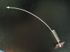
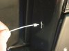
Saturday, January 19. Crisp, clear day. About 40 degrees. Pavement dry. We had just finished installing the headers the evening before; the very last item on the list before it was road ready. Time for the Ryan and me to take our first drive after more than six months of rebuilding the GT and see how the new shocks, springs, engine, Webers, and gauges performed.

First stop: the Shell gas station to top off the two tanks with some 93 octane. Pulled up and started to fill the passenger side tank when a fellow comes by and asks the usual questions. Nice enough guy who was genuinely impressed and appreciated the information we shared with him.

The hose won't reach across the front clip, so when the right tank was full the transaction was concluded, receipt generated, then started up and moved the GT to the other side of the same pump so the process could be repeated for the driver's side tank. Half way through filling it an old Chevy pick up, with deteriorating white paint, pulls up close. The driver lowers his window. A lad, perhaps around 30, wearing a knit multi pastel colored cap with the remnants of a tassel on top, the ties hanging along side his full red beard, is driving. He says almost nothing about the GT, but proceeds to share his experience with his mid 70's Vette that he is restoring. Got the engine done and is getting ready to paint it. "It is white. Hate white. That is a trailer trash color. Don't you agree. Going to paint it black. Don't you agree?" Looking at his selection of head gear and the color of paint on the conveyance he was occupying, I was not sure how to answer, so a noncommittal nod of the head was about as much response I deemed appropriate. I feigned being preoccupied with the fuel level in the tank and he started to drive away, yelling when he reached the other side of the gas station "so you think white is a trailer trash color?" We got our second receipt and headed for the road.

Out on the Interstate, Ryan driving, cruising in reasonable proximity to the legal speed limit, a small older Subaru, white in color as I recall, pulled up alongside, matching our speed for a bit. Presumably that was his girlfriend in the passenger seat. Then he down shifted his automatic and darted ahead of us. It had one of those big rice burner tail pipes that made a rattly sound we could just hear over the melody of our own power plant as he buried the right pedal. We were so impressed. I am sure his girlfriend was too.

About five miles after exiting the interstate we pulled up to a red stop light. Even at idle the roar of nearly 500 horses just behind the seat and straight exhaust makes casual conversation with the person rubbing shoulders alongside a challenge. So when an older model car pulled up alongside and rolled down the window to engage in conversation we had to wonder: what trailer court did they come from? But their car was faded red, not white. Watching the lips of the girl in the passenger seat it looked like she was saying "What is it." Could have been "You eat shit" for all I know. Ryan and I looked back and simultaneously lipped "GT40". She nodded, as if she understood. Yea, sure.

You meet the most interesting people driving a GT 40!
 
Great story Chuck. How did the car feel? Could you notice any significant differences than the first generation? It's kind of nice to be able to actually experience the car with different setups.

Impressed as usual....
 
Check & Tom
Chuck, it sounds like you solved your suspension issues and had a good drive, which after all what its all about.
I read your posts with interest and in my experience as Tom says the upright will swing in relation to the wishbones at 90 deg. to the pivots.
The issue you will encounter is that your upper wishbone is probably angled upward to the front, most likely about 2 or 2 1/2 deg. to introduce anti-dive into the front end. You don't need much in a chassis like yours as there is not the same amount of weight transfer like you would have in a large front engined vehicle (Take a look under the hood of a bigger vehicle at the upper mounts).
This mounting angle does affect the swing of the upper wishbone, and it does swing rearward slightly as it moves thru its travel...the good news is there is not a great amount of travel in these suspensions, and it does not affect performance enough to be a real problem as evidenced by your drive.
Mostly the caster angle increases slightly and thats not a problem.
In my experience its really difficult to remove all bump steer, and if you get a happy compromise such as you have and the car drives well just go with it.
Cheers
Phil
 
Last edited:

Chuck

Supporter
Phil: Good points. When I next have the front clip and/or wheels off need to check to see if the upper has a bit of 'anti dive' or is indeed parallel to the lower. No real hurry and more a matter of curiosity since the suspension feels great and bump steer does not appear to be an issue.

I suspect that doubling the spring rate from 300 to 650 on the front may have also had a favorable affect, keeping the amount of suspension travel closer to the 'sweet spot.'
 

Chuck

Supporter
Thanks Fran. Now I don't have to pull off a wheel to find the answer. Was wondering when you would chime in . . . .
 
Check & Tom
Chuck, it sounds like you solved your suspension issues and had a good drive, which after all what its all about.
I read your posts with interest and in my experience as Tom says the upright will swing in relation to the wishbones at 90 deg. to the pivots.
The issue you will encounter is that your upper wishbone is probably angled upward to the front, most likely about 2 or 2 1/2 deg. to introduce anti-dive into the front end. You don't need much in a chassis like yours as there is not the same amount of weight transfer like you would have in a large front engined vehicle (Take a look under the hood of a bigger vehicle at the upper mounts).
This mounting angle does affect the swing of the upper wishbone, and it does swing rearward slightly as it moves thru its travel...the good news is there is not a great amount of travel in these suspensions, and it does not affect performance enough to be a real problem as evidenced by your drive.
Mostly the caster angle increases slightly and thats not a problem.
In my experience its really difficult to remove all bump steer, and if you get a happy compromise such as you have and the car drives well just go with it.
Cheers
Phil

Exactly, thats the reason why i pointed out that both a arms in one plane (parallel)to each other.
I have dialed in my bumpsteer to 0 mm from rideheight to full compressed. I have 0,2mm toe change ( don´t even remember if toe in or out ) measured on the 7,5" radius from wheel center (=0,06°=3'36" in the last 0,5" of full out travel ( car will never reach this point as long it is not airborn).
This with the orginal RCR steering rack position and only modified steering arms with shortened tierods and inner tierod hinge point moved outwards by 15mm ( it think). The actual RCR steering arm on RCR 40´s are modified the same way as mine ( Fran and me had the same idea at the same time).

TOM
 

Chuck

Supporter
Great story Chuck. How did the car feel? Could you notice any significant differences than the first generation? It's kind of nice to be able to actually experience the car with different setups.

Impressed as usual....

Jim:

Will post a more objective response when time permits. In the meantime . . . .

Our first post rebuild ride was on Saturday. Monday, when senior engineering students had the day off, Ryan took the GT for its second post rebuild drive. Here is the message he texted me as I toiled away at the office:

It was epic. This car is awesome. Throttle feels much better. Put the foot down in fourth gear, 3000 RPM, 60 mph . . . . WHEEL SPIN! My dreams have come true.

I then messaged him if he could tell a difference with the prior engine. His response:

Well. . . . I couldn’t get the wheels to spin beyond second gear . . . . So yes, massive improvement. This car is awesome.

It is looking like we may need to upgrade the tires sooner rather than later.
 
Back
Top