
You are using an out of date browser. It may not display this or other websites correctly.
You should upgrade or use an alternative browser.
You should upgrade or use an alternative browser.
Chuck and Ryan's RCR Build
- Thread starter CESLAW
- Start date
Hi Chuck
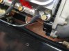
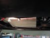
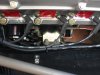
Some pics of tanks and 4 x fixings


Some pics of tanks and 4 x fixings
Hi Chuck
Some pics of tanks and 4 x fixings View attachment 61614
View attachment 61615
View attachment 61616
I like that idea as well!
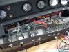
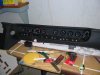
Gauges, Wiring Completed
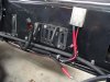
Switch panels. The switch panels were replaced. About five inches of slack permits the switch panel to be removed and folded back to provide better access. They were repainted the same Fusion flat black as the rest of the dashboard before being reassembled.
Testing. A firm believer in checking circuits, the dash was temporarily set in place and the various plugs connected to their mates on the chassis. (Every connection to the dash is through a GM style plug to facilitate removal of the dash). The headlights were switched on and immediately the gauges all glowed a soft white with a white needle. The rheostat (mounted just to the right of the steering column on the underside of the dash, out of sight but easily reached) worked very well changing the brightness of the lights.
The ignition was turned on. The volt gauge immediately jumped to 12 volts. Next the fuel gauge sender wires were grounded and the needle slowly swung to the full mark. There is some electronic dampening going on here, since it moved slowly, which will eliminate that annoying needle bounced when accelerating and braking seen with many other gauges.
The fuel gauges come with a switch that plugs into the back for calibration purposes. Since the gauges are pre set to 33 - 240 ohms, and since that matches the senders, no calibration is needed. The speedometer also comes with a remote calibrations switch, but since there is a switch mounted on the front side it is not needed.
Next the oil and water temp sender wires were grounded. They also slowly moved full scale. The only gauge we were not able to check was the oil pressure gauge.
With the gauges now wired and checked, the dash was removed so additional projects could be tackled.
Attachments
Last edited:
Engine Prep
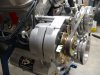
Before installing the new engine there were a few little items to address.
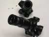
The previous engine had a 100 amp polished GM style one wire alternator with chrome fan and pulley. It worked just fine, but something a bit more vintage was preferred. So we replaced it with an 80 amp GM style one wire alternator with a natural aluminum finish. Tuff Stuff #7127. The case is the same size as the prior alternator so the same bracket was used. We expect the 80 amps to be more than adequate.
Although the Roush bracket is not vintage, it is solid as a rock and is not really seen once installed. We buffed it with a Scotch Brite pad to dull the sheen.
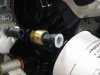
The new water temp and oil pressure senders for the Speed Hut gauges were installed. The oil pressure sender is nice and compact, so no extensions were needed; only an adapter 1/8 x ½ pipe reducer. Russell thread sealer was used on all the senders.
Some minor details in the engine compartment were addressed. The shifter cables were secured with clamps rather than tying them off. The control arms were repainted.
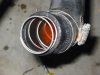
The hose from the intake of the water pump to the stainless steel tube running through the center section is about a foot long. To prevent it from collapsing from the suction forces of the water pump a wire insert was added. The one we used was intended for a 1965 Ford Mustang. One literally screws it in. It made the hose noticeably more rigid. I had been losing sleep wondering if that hose would collapse when we exceeded 150 mph with this new power plant. I will sleep better tonight now that this issue has been addressed.
Before installing the new engine there were a few little items to address.
The previous engine had a 100 amp polished GM style one wire alternator with chrome fan and pulley. It worked just fine, but something a bit more vintage was preferred. So we replaced it with an 80 amp GM style one wire alternator with a natural aluminum finish. Tuff Stuff #7127. The case is the same size as the prior alternator so the same bracket was used. We expect the 80 amps to be more than adequate.
Although the Roush bracket is not vintage, it is solid as a rock and is not really seen once installed. We buffed it with a Scotch Brite pad to dull the sheen.
The new water temp and oil pressure senders for the Speed Hut gauges were installed. The oil pressure sender is nice and compact, so no extensions were needed; only an adapter 1/8 x ½ pipe reducer. Russell thread sealer was used on all the senders.
Some minor details in the engine compartment were addressed. The shifter cables were secured with clamps rather than tying them off. The control arms were repainted.
The hose from the intake of the water pump to the stainless steel tube running through the center section is about a foot long. To prevent it from collapsing from the suction forces of the water pump a wire insert was added. The one we used was intended for a 1965 Ford Mustang. One literally screws it in. It made the hose noticeably more rigid. I had been losing sleep wondering if that hose would collapse when we exceeded 150 mph with this new power plant. I will sleep better tonight now that this issue has been addressed.
Attachments
Engine installed
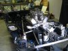
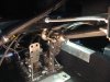
Ryan and I installed the engine and transmission without fanfare. It seems to get easier each time we do it.
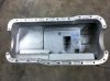
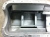
The real surprise was the oil pan. An Aviad oil pan, specific to the GT40, part number 155-55361 was used rather than the Canton pan. This is a very nice product. It is 6 ½” deep rather than the usual 7 ½. More significantly, the sump is a good inch narrower than the pans typically used on the GT40 reproductions. The Aviad makes up for the shallower and narrower sump by extending the sump back further. It holds 6 quarts (probably seven with the filter and plumbing).
There are a host of wires, oil lines and hoses running through the engine compartment. With the Canton pan it was a real challenge making everything fit. With the Aviad, however, there is plenty of room with actual space left. It was such a pleasure working under the car with that extra room to maneuver. (Note pictures)
When installed the bottom of the pan is about a quarter inch above the bottom of the chassis. With the Canton pan, it set a half inch below.
The pan is well baffled. There are two plugs: one is a drain and the second is for a temperature sender. Both have small wire ties welded nearby to safety wire the plugs. Nice touch.
If shopping for an oil pan, check out the Aviad GT40 specific pan.
Ryan and I installed the engine and transmission without fanfare. It seems to get easier each time we do it.
The real surprise was the oil pan. An Aviad oil pan, specific to the GT40, part number 155-55361 was used rather than the Canton pan. This is a very nice product. It is 6 ½” deep rather than the usual 7 ½. More significantly, the sump is a good inch narrower than the pans typically used on the GT40 reproductions. The Aviad makes up for the shallower and narrower sump by extending the sump back further. It holds 6 quarts (probably seven with the filter and plumbing).
There are a host of wires, oil lines and hoses running through the engine compartment. With the Canton pan it was a real challenge making everything fit. With the Aviad, however, there is plenty of room with actual space left. It was such a pleasure working under the car with that extra room to maneuver. (Note pictures)
When installed the bottom of the pan is about a quarter inch above the bottom of the chassis. With the Canton pan, it set a half inch below.
The pan is well baffled. There are two plugs: one is a drain and the second is for a temperature sender. Both have small wire ties welded nearby to safety wire the plugs. Nice touch.
If shopping for an oil pan, check out the Aviad GT40 specific pan.
Attachments
Half Shafts
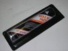
While off the car, the half shafts were cleaned and sprayed with Fusion Satin black, our new favorite trim and touch up paint.
We had been using plain old grease to lubricate the half shafts. However, one should use a high pressure lubricant, preferably molybdenium disulfide based. There are several possibilities, but Honda Moly 60 Paste reportedly has the highest concentration of moly and is used specifically in applications like this. We found several suppliers on E Bay. It comes in 3 ounce tubes, so we ordered two. A good even coat was applied. Less than one three ounce tube was needed.
When rejoining the halves one must be careful to keep the ends aligned or a nasty vibration will set in when the car is driven.
Both the rear and front suspension are now reassembled.
Attachments
Tom:
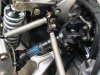
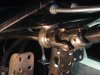
You have a sharp eye. The rod ends will not fit on the top side due to the head of the bolt that passes through the transmission cross bar support. By putting the rod end bolt in from the bottom there is enough clearance. We have many miles with this arrangement and the clearance is fine. With the stiffer springs we are now using it should be even less of an issue. The photo I posted is a bit deceiving in that it makes it look closer than it is.
The oil pan gasket is a Mr. Gasket MRG 5890.
Chuck
Chuck,
The rod end will clear with a spacer and it may even help improve the 'triangulation' between the two rods and underbelly tray. I know that Fran has stated before that there is enough clearance between that rod end nut and half shaft but I want to play it safe during my initial road tests.
Tom
The rod end will clear with a spacer and it may even help improve the 'triangulation' between the two rods and underbelly tray. I know that Fran has stated before that there is enough clearance between that rod end nut and half shaft but I want to play it safe during my initial road tests.
Tom
Attachments
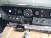
Steering
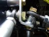
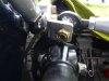
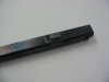
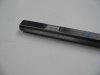
The steering support that mounts under the dash had a bit of play which was not really significant, but noticeable. With the GT torn apart this was a good time to address the issue. The flattened steering shaft passing through the round opening was the culprit. We wanted to close the gap.
A bead was welded on the flat surfaces of the shaft where it passes through the support. It was then turned on a lath to produce a smooth round surface to mate with the opening of the support. This significantly reduced the movement and made the steering column free of any flex. Be sure to lubricate the shaft in this location, since it rotates within the support.
The only play remaining in the steering now is in the quick release hub.
Attachments
Steering
The steering support that mounts under the dash had a bit of play which was not really significant, but noticeable. With the GT torn apart this was a good time to address the issue. The flattened steering shaft passing through the round opening was the culprit. We wanted to close the gap.
A bead was welded on the flat surfaces of the shaft where it passes through the support. It was then turned on a lath to produce a smooth round surface to mate with the opening of the support. This significantly reduced the movement and made the steering column free of any flex. Be sure to lubricate the shaft in this location, since it rotates within the support.
The only play remaining in the steering now is in the quick release hub.
NICE!
Chuck
are you still using the holley 125 fuel pump with new rcr fuel tanks?
Holley says pumps need to be mounted below fuel tank if so how does the fuel pump draw fuel from the gas tank,is your fuel pump above your fuel tank?also does your fuel tanks have baffles mine does not do i need baffles for a street car i hope not i do not want to cut up these nice fuel tanks i have.
Thanks wayne
Wayne...
if you want to add fuel foam , available from Jegs/Summit etc there is no need for baffles...but be careful you chose the right kind of foam , if you plan on running Ethanol based fuels with your supercharger.
if you want to add fuel foam , available from Jegs/Summit etc there is no need for baffles...but be careful you chose the right kind of foam , if you plan on running Ethanol based fuels with your supercharger.
Wayne
Yes, still using the Holley fuel pumps. They work splendidly. Although mounted just above the level of the tanks they have no problem pumping fuel. In an early post when we originally built the car I believe we posted a picture of the stream it put out. A bit pricey, but reliable and quiet.
As Fran noted, we used foam in the tanks. Specifics on a prior post.
Chuck
thanks for response,summit says sponge could hit fuel sending unit they said i need a special sending unit witch unit did you use?also how did you vent your new tanks?
Thanks wayne
1. The sending units are a capacitance / inductive unit that come with the Speed Hut gauges. Also cut an opening in the section of foam that sets around the sending tube.
A conventional float type sender would not be a good choice with the foam
2. The new tank has a threaded fitting so the same vent was used as was used with the original tank.
Similar threads
- Replies
- 0
- Views
- 538
- Replies
- 1
- Views
- 459