
You are using an out of date browser. It may not display this or other websites correctly.
You should upgrade or use an alternative browser.
You should upgrade or use an alternative browser.
Arrangement drawings from grabcad (?)
- Thread starter turb00le
- Start date
Nope, grid spacing is probably 400mm. Atleast when scaled to 400mm most other dimensions add up with fav drawings, wheelbase etc. and alot of other details seems to be correct (ex the angled axis between pivot points to create anti dive).I have no idea where they came from.
The grid used in the files does not appear to be consistent with the 10" grid used throughout the rest of the files.
Will try to do some overlays with an assembly based on fav drawings to see how it looks.
Doc Watson
Lifetime Supporter
They are cad drawings from when Ray Webber was making chassis based on a CCD chassis imported from NZ.
Cheers.They are cad drawings from when Ray Webber was making chassis based on a CCD chassis imported from NZ.
Any idea how accurate or inaccurate they might be?
Doc Watson
Lifetime Supporter
Ray spent a long time getting the tooling and jigs correct so I would say as accurate as is possible. I also know he had a few original chassis in the workshop to check.
Is this the Mirage chassis that @JIMMYMAC and Alistair are using?They are cad drawings from when Ray Webber was making chassis based on a CCD chassis imported from NZ.
Jimmymac & Alistair's Cars | GT40s
Cheers.
Any idea how accurate or inaccurate they might be?
I take my hat off to anyone that has a go. It takes an inordinate amount of time to understand the chassis, and another inordinate amount of time to work out how to construct it and get it close to accurate with the drawings and tooling you have available. It is fun though. Its not something that someone can say "do it like this or that" because everyone will have different skills/space/tooling. There is stuff your just going to have to go though and work out for yourself.
JimmyMac
Lifetime Supporter
They are cad drawings from when Ray Webber was making chassis based on a CCD chassis imported from NZ.
Those GAs are not Ray's CAD drawings. We have a set of drawings that he and Steve made including the press tooling and his complex jig table.
Guess we just went back to start againThose GAs are not Ray's CAD drawings. We have a set of drawings that he and Steve made including the press tooling and his complex jig table.

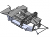
I am at the point where i can get all pivot points and main elements within a few mm, pretty confident that i could have a complete and correct 3d model in solidworks with flat patterns etc. I have done a few alterations to facilitate cnc cutting and bending but kept main dimensions.I take my hat off to anyone that has a go. It takes an inordinate amount of time to understand the chassis, and another inordinate amount of time to work out how to construct it and get it close to accurate with the drawings and tooling you have available. It is fun though. Its not something that someone can say "do it like this or that" because everyone will have different skills/space/tooling. There is stuff your just going to have to go though and work out for yourself.
In order to understand the construction one had to draw everything from the fav drawings and place on the coordinates stated on drawing.
The problem i soon ran into is the lack of information (i.e. drawings) other then those sold on ebay/downloaded from grabcad.
Since I don't have any info on uprights, suspension arms (other than a couple of SPF sketches).
So probably i will end up with a monocoque which is 60-70% authentic in shape and dimensions but with a different suspension setup and extended frontbox for leg space.
Doc Watson
Lifetime Supporter
I stand corrected (said the man in orthopedic shoes)...
When I bought my drawings the write up said the two cad files were from Ford Racing Division and are 100% accurate.
Yes, I found an ad on eBay where the same is stated. If you look at the elevation view you can see some markups for example to raide the cutout for radius arms.When I bought my drawings the write up said the two cad files were from Ford Racing Division and are 100% accurate.
I hope to finish the 3d model with what i have within a couple of weeks. Will do an overlay to see how it looks.
Well, its coming along nicely, still a shitload of hours if one wants to complete it.
I am now at the point where i leave the original design and implement my own changes (some already made);
-Conventional double A arms rear suspension instead of radius arms.
-Remove the "chamfer" in the front corners to get more space for pedals, maybe some cutouts for master cylinders etc in the nose section.
-Front a arms pivot points paralell to centerline of the car.
Attachments
Still "investigating".
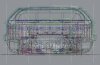
Borrowed (sounds better than stole) a picture from jimmymac's build thread.
Converted the PDF in the first post to dxf and put them on top of eachother with some transparency.
The dxf conversion is a bit unclear/blurry due to the pdf being a scanned print.
They are quite close but can't say that they originate from ray, if so maybe from an early stage based on the markups and that they were adjusted.
If someone is in posession of information/drawings/something that might be handy i'm interested...
At this stage i'm not going to model a true copy of the original tub but i see that it is fully possible to do with some minor alterations to allow for cnc cutting and bending. Compound faces is not solidworks or inventors best friend...
Attachments
If someone is in possession of information/drawings/something that might be handy I'm interested...
I have been looking at these plans for a while now and cant remember what I have and where I got them from. I have found that if I have asked for specific information about a particular panel, then I have had better luck as it helps locate the drawing that someone may have.
There were some excel files getting around that had drawing lists in them. There are probably still more drawings out there.
Yup, there are quite a few drawings to choose fromI have been looking at these plans for a while now and cant remember what I have and where I got them from. I have found that if I have asked for specific information about a particular panel, then I have had better luck as it helps locate the drawing that someone may have.
There were some excel files getting around that had drawing lists in them. There are probably still more drawings out there.

Would be sweet with more details of the rear bulkhead and windscreen frame/a pillars atm.
Might be able to extract information from drawing 2000 (chassis complete drawing) if that includes the spider and rear bulkhead.
Don't have drawing numbers for rear bulkhead items.
With the drawings available on grabcad it is possible to draw most of the tub up to the bottom of the windscreen.
Sometimes assembly drawings which lack dimensions has to be imported to autocad, scaled correctly and measured visually with a dist command.
I have not found drawings of the roof structure. At the end of the day i will probably just make this match the bodywork that I have. We know where the top of the side sill finishes and its width. the angle will match the rear body work and it will just go up from there. If i get to that stage, I think i will have amassed enough metal working skill to keep going.
If you spend enough time looking at photos you will notice that there were changes as ford went through production. I think I have also seen some changes between the early Superformance cars and the later ones as well as some differences between away from the drawings as well to facilitate modern needs. Still great cars.
The challenge and enjoyment for me is working out how they were folded up, what order and processes were used, what tooling and tricks. Its great when you stumble on that little bit of information and clarity of your thoughts is achieved.
Ryan
Similar threads
- Replies
- 0
- Views
- 263
- Replies
- 1
- Views
- 604