Feedback on Frame Design – Over-Engineered or Solid?

Hey everyone,


I’ve been working on designing a frame for my project and I’m at the point where I’d really appreciate a second opinion from people who know their stuff.


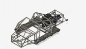
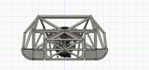
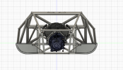
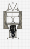
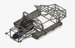
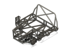
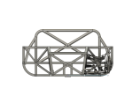
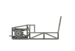
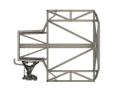
The main chassis frame is made from 1.5” steel tubing, and the roll frame is 2” steel for added strength and safety. I’m trying to strike a good balance between strength, weight, and fabrication simplicity, but I’m starting to worry that I may have over-complicated the design with extra bracing and geometry that might not actually add much benefit.


If anyone’s willing to take a look and let me know if it looks solid or unnecessarily complex, I’d appreciate it. I’m aiming for something that can handle real-world loads safely but don’t want to make life harder on myself if I don’t need to.


Let me know if you need more specifics or drawings to give feedback. Thanks in advance!
 

Attachments

  • Screenshot 2025-06-19 134209.png
    Screenshot 2025-06-19 134209.png
    1 MB · Views: 332
  • Screenshot 2025-06-19 134217.png
    Screenshot 2025-06-19 134217.png
    242.4 KB · Views: 286
  • Screenshot 2025-06-19 134319.png
    Screenshot 2025-06-19 134319.png
    243.2 KB · Views: 268
  • Screenshot 2025-06-19 134328.png
    Screenshot 2025-06-19 134328.png
    220.7 KB · Views: 272
  • Screenshot 2025-06-19 134421.png
    Screenshot 2025-06-19 134421.png
    1 MB · Views: 316
I plan on using 0.120" thick steel. It's a little on the heavy side being 600-650 lbs, but I rather error on the side of safety than being light as I'm planning on using an ls3 engine which will probably produce 40-450+ HP.
 
I plan on using 0.120" thick steel. It's a little on the heavy side being 600-650 lbs, but I rather error on the side of safety than being light as I'm planning on using an ls3 engine which will probably produce 40-450+ HP.
A chassis & cage of 1,5" OD with an 0.090" wall should be OK. The roll cage & chassis should be built with seamless SAE 1020 mild steel tubing. This allows the structure to deform plastically in a collision, absorbing energy as it deforms. I think you can greatly simplify your structure without much compromise in safety.

My friend Rob crashed his streamliner at Bonneville a few years ago. He was traveling at 432 mph when things went wrong. The car became airborne, tumbled and rolled for more than a quarter mile before it came to a stop. Rob survived-- his chassis and cage did its job. Even so, the high "G" forces produced a closed brain injury, similar to a stroke. He has recovered but not 100% A stronger structure does not always add more protection.

Carbinite Streamliner a.jpg
 
I'm sorry to hear about your friend. Thank you for the advice about tube thickness, based on what you see do you have any areas I could remove any structural elements?
 

Ole Nylende

Supporter
As above; You need triangulation on the sides of the structure.
I would recommend that you define the pickup points for your suspension, especially the shock/spring mounts.
This is where your loads will act to try twisting the chassis, areas you need to focus on triangulation and reinforcements.
If you are going to use corvette bits bremar has got scan data for purchase online...
In a few areas you have added triangulation in both directions plus a horizontal tube, this seems a bit overkill.

Also consider;
Round tubing is nice strengthwise but will add alot of complexity during fab and in areas where you are to close up with plates (which is quite a few in the end)
Square and rectangular tubing is in my opinion easier to work with and get good fitment to avoid alot of stress and distortion after welding.
Maybe you could combine round and square sections and make some of them detachable for easy servicing?
 

Pedro

Supporter
You may want to take a look at this build, lots of good information here.


Mike Pass

Supporter
Cheers
Mike
 
I'm sorry to hear about your friend. Thank you for the advice about tube thickness, based on what you see do you have any areas I could remove any structural elements?
The first chassis that I designed and built was for my Sabel Mk III. I generally followed the guidelines outlined in Costin & Phipps "Racing and Sports Car Chassis Design". In addition, I built a model of the space frame out of 1/8" balsa wood. Then I applied torsional loads through the suspension pick-up points and saw what broke. Later I had access to an IBM 360 Mod 50 and a structural engineering program called "STRUDL", so I could accurately measure the stresses in each tube. Build a balsa model of your chassis and see the results. Modify it and try again. It is highly instructive!
 
Rowan,If you have not seen my build diary, you may find it helpful.


The video was made of photos that I took over a period of years and it isn't in chronological order- painted chassis, unpainted chassis, etc. This structure was built to conform to the SCTA rules for Bonneville. "SCTA" = Southern California Timing Association.

I employed nickel silver braze welding rather than TIG or MIG. I prefer a torch and this alloy is bead- forming and has about 85,000 psi tensile strength. A small "aircraft" torch is large enough for braze welding as it requires less heat than fusion welding.
 
Thank you all for your suggestions. I have redesigned from the front of the primary structure to the back of the cabin. I have implemented the following design changes.
-Square tubing for ease of manufacturing, except for the roll bar
-More triangulation for the front
-Decided on using the front and rear suspension from a C5/C6 since that seems to be a popular for these types of builds.
-I decided to remove the front roll bar as the overhead bars connecting the front and rear could cause possible issues with the occupants heads.

I plan on adding sheet steel over the space frame for additional strength and to provide a smooth surface, so it would be a mix between space frame and a monocoques. I did have some issues properly fitting the C5 front suspension because its so wide, which causes the track width to be wider than the original.
 

Attachments

  • Screenshot 2025-07-08 220045.png
    Screenshot 2025-07-08 220045.png
    645.4 KB · Views: 235
  • Screenshot 2025-07-08 220032.png
    Screenshot 2025-07-08 220032.png
    212.5 KB · Views: 225
  • Screenshot 2025-07-08 220018.png
    Screenshot 2025-07-08 220018.png
    120.4 KB · Views: 198
  • Screenshot 2025-07-08 220008.png
    Screenshot 2025-07-08 220008.png
    230.4 KB · Views: 232
To give you a reference point, here's a chassis I built for a Ferrari 250GTO recreation. Yes, it's a front engine chassis (well mid-engine but with block in front of driver instead of behind) so it's not exactly the same as a GT40. It uses C5 Corvette suspension and is composed mostly of 1.5" .090 wall seamless tubing, roll cage is 1.5 .125 wall, and triangulation tubes a mix of 1" and .75 in a lighter wall thickness. When I first designed the chassis, I had the plans reviewed by a knowledgeable chassis guy and his input was that I had over done some of the triangulation and these pictures are of the simplified design.

DSCF0066.JPG


DSCF0067.JPG


DSCF0068.JPG


DSCF0070.JPG


The car is powered by a supercharged LS and has right at 500 rear wheel horsepower. The handling is fantastic!! I'm now a big fan of the C5 suspension design. I used the full cast aluminum cradles from the C5. If I did it again, I might not use them just because they are relatively heavy. But they do simplify the chassis fabrication by holding lower control arms, sway bars. transaxle mount, R&P steering, etc. all with a straight forward 4 bolt mount.

With the engine placement back about 12" from the standard C5 location and the use of the 6 speed manual transaxle the car has 56% of static weight on rear wheels and weighs in at 2,830 lbs. I used coil overs instead of transverse fiberglass springs which enables the chassis corner weights to be dialed in.

I don't know if this will help you with your chassis design questions but I thought it wouldn't hurt.
 
I would suggest you reconsider the front roll bar and tie it to the rear roll bar as in the MARK II GT-40. It will stiffen the chassis considerably when you add a tying piece outboard. Look at the original Mark II's. Yes, it looks like it is in the way when you open the door, but it actually makes getting in or out easier and really stiffens the chassis, I believe your original drawing did not have this tube. I never found this bar to be a problem while in the car or on entry or exit. You seem to have addressed some of the center section stiffness issue in your revised drawings. Have you considered how you are going to run the cooling lines? Consider running the lines down the middle of the car by using a rectangular tube backbone. Say a 3X4, so it can do double duty as part of the chassis and hide the cooling tubes. This is the way it was done in the MK IIA's. You will have to cut an opening in the front section of this tube so the cooling lines can come out to the radiator. Just a thought, nice job.

BillK
 
I would suggest you also need a cross brace on the rear hoop going from low down on passenger side to high up on driver side.. This will stop the whole cage from leaning over in the event of roll over.

Jerry
 
Back
Top