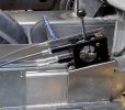
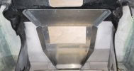
Thought I would share some pics of what's all happening with my GT40 project. I have really enjoyed this site lots of great information. The E brake has to be fit in yet I just wanted to clean up the look with console..


You are using an out of date browser. It may not display this or other websites correctly.
You should upgrade or use an alternative browser.
You should upgrade or use an alternative browser.
Wisconsin GT40
- Thread starter H FURO
- Start date
Very nice Harold. Looks good.
Regards Brian
Regards Brian
No concerns all of them tighten up. that pic is with studs in the holes it will have the correct bolts installed on finial assembly. These bolts are just for mock up.Any concerns about three long bolts providing sufficient lateral support when the belt is tightened?
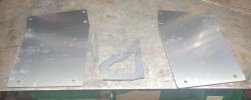
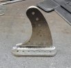
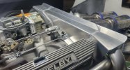
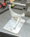
Was going thru some pics and found a pic of the shifter parts I cut out on my cnc table. I dropped the back down so the cables are lower to go thru fire wall. I can make these as I have file to cut them now.Thought I would share some pics of what's all happening with my GT40 project. I have really enjoyed this site lots of great information. The E brake has to be fit in yet I just wanted to clean up the look with console.. View attachment 151147
Attachments

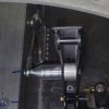
Here are some more parts I made up for the throttle linkage and brackets from pedal to carb all done. For those that have asked all these parts can be duplicated. I have a lot of ideas and will be making a lot more stuff.
Attachments
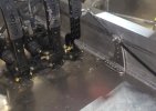
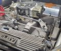
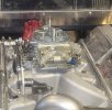
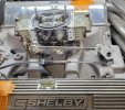
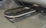
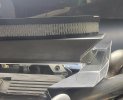
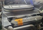
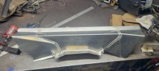
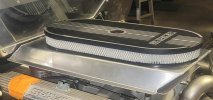
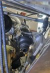
Air cleaner to body.......For those that messaged me in regards to how the air cleaner base and the rear cap fits together heres some pics. When the body is lowered down it fits in between the heat shield and the air cleaner base.

.jpg")
Attachments
Hi Chuck, Thank you for bringing up the heat issue with the carb. This is why I joined this site and is so well respected. I have always had a open mind and I want to learn more about these builds. Any suggestions you or others can help help me with would be greatly appreciated, this is how we all learn.Any concerns about excess heat being trapped around the carb?
Thank you,
Furo
Furo:
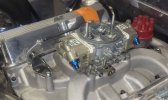
My RCR GT-40 has gone through three rebuilds. The second engine featured a Holley carburetor. I wanted an induction system that would look like an original. Here is what I did.
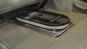
An oval air cleaner was used. A reversion plate was then fabricated to sit atop the air filter. Once in place, a casual observer would be hard pressed to realize that a Holley rather than four Webers were feeding the engine.

This also permitted free movement of air around the engine. Heat buildup is an issue.
Here is a link to the post from 16 years ago that discusses that project in detail. https://www.gt40s.com/threads/chuck-and-ryans-rcr-build.22083/post-306876
I may still have the pattern for the reversion plate if you are interested in the dimensions, although the details are included in the referenced post. It looks like you have welding skills, so fabricating the reversion should be a straightforward project.
My RCR GT-40 has gone through three rebuilds. The second engine featured a Holley carburetor. I wanted an induction system that would look like an original. Here is what I did.
An oval air cleaner was used. A reversion plate was then fabricated to sit atop the air filter. Once in place, a casual observer would be hard pressed to realize that a Holley rather than four Webers were feeding the engine.
This also permitted free movement of air around the engine. Heat buildup is an issue.
Here is a link to the post from 16 years ago that discusses that project in detail. https://www.gt40s.com/threads/chuck-and-ryans-rcr-build.22083/post-306876
I may still have the pattern for the reversion plate if you are interested in the dimensions, although the details are included in the referenced post. It looks like you have welding skills, so fabricating the reversion should be a straightforward project.
If you have the patterns that would be a great help. Thank you, FUROFuro:
My RCR GT-40 has gone through three rebuilds. The second engine featured a Holley carburetor. I wanted an induction system that would look like an original. Here is what I did.
An oval air cleaner was used. A reversion plate was then fabricated to sit atop the air filter. Once in place, a casual observer would be hard pressed to realize that a Holley rather than four Webers were feeding the engine.
View attachment 152243
This also permitted free movement of air around the engine. Heat buildup is an issue.
Here is a link to the post from 16 years ago that discusses that project in detail. https://www.gt40s.com/threads/chuck-and-ryans-rcr-build.22083/post-306876
I may still have the pattern for the reversion plate if you are interested in the dimensions, although the details are included in the referenced post. It looks like you have welding skills, so fabricating the reversion should be a straightforward project.
Thank youFuro
Here is the pattern. The mounting holes shown were for the Weber carbs. With a four-barrel and conventional air cleaner, a single hole would be needed, with the specific location to be determined to assure clearance when the clip is opened.
View attachment 152285
This is how Ford did it running a Holley on a GT40.
A box from below the carb as a heat shield.
In my opinion, the box you made acts as a heat trap for the carb.

A box from below the carb as a heat shield.
In my opinion, the box you made acts as a heat trap for the carb.
Similar threads
- Replies
- 1
- Views
- 564
- Replies
- 21
- Views
- 2K