
You are using an out of date browser. It may not display this or other websites correctly.
You should upgrade or use an alternative browser.
You should upgrade or use an alternative browser.
Alans Scratch build
- Thread starter hiiesalu
- Start date
Ed McClements
Supporter
Hi Alan
Hard to see from the pics, but is the upper balljoint slightly ahead of the lower balljoint? I think you want it slightly behind, to give you some caster angle.
Eddy
Hard to see from the pics, but is the upper balljoint slightly ahead of the lower balljoint? I think you want it slightly behind, to give you some caster angle.
Eddy
Thanks for that, On the C5 suspension would you know toe and camber. The upper ball joint seems to have adjustment for camber. If I adjusted them in a position and tack welded the mount brackets, then had enough adjustment to get proper camber before final weld. The body should arrive in a few weeks . Any info greatly appreciatedHi Alan
Hard to see from the pics, but is the upper balljoint slightly ahead of the lower balljoint? I think you want it slightly behind, to give you some caster angle.
Eddy
Joel K
Supporter
Thanks for that, On the C5 suspension would you know toe and camber. The upper ball joint seems to have adjustment for camber. If I adjusted them in a position and tack welded the mount brackets, then had enough adjustment to get proper camber before final weld. The body should arrive in a few weeks . Any info greatly appreciated
c5 and C6 front suspension are very similar. To adjust camber on the top control you can use shims of various thickness between the control arm mounting point On the chassis and the upper control arm bushing rod.
Ed McClements
Supporter
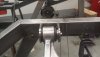
I was talking about caster angle...the upper balljoint being slightly rearward of the lower balljoint...giving some steering stability and self-centering effect. One way to make this adjustable would be to make provision for spacers here:-

To allow for the upper arm to be moved rearwards to add caster.
To allow for the upper arm to be moved rearwards to add caster.
Thanks for the spacer idea, this forum is great.I was talking about caster angle...the upper balljoint being slightly rearward of the lower balljoint...giving some steering stability and self-centering effect. One way to make this adjustable would be to make provision for spacers here:-
View attachment 107167
To allow for the upper arm to be moved rearwards to add caster.
And thanks for the drawing. I will make several thicknesses spacers on the latheThanks for the spacer idea, this forum is great.
Follow up assuming upper and lower are at the even point, how much rearward should it be, say 3 washers at .100 each would allow .300 to the rear. Or different combationsThanks for the spacer idea, this forum is great.
.200 .300??
What would you suggest
Thanks so much
Ed McClements
Supporter
Others might chime in here (@wealdenengineer , @Jim C maybe...?) but you might wish to start with around 5 or 6 degree caster as the mid-point setting, with the ability to add or remove a couple of degrees. Take a look in the "Tech - chass / brakes / tyres / wheels" sub-forum:-
As Frank said...https://www.gt40s.com/threads/settings-camber-toe-shocks.52994/post-534583
Good luck, and keep us posted!
As Frank said...https://www.gt40s.com/threads/settings-camber-toe-shocks.52994/post-534583
Good luck, and keep us posted!
Bill Kearley
Supporter
Start with setting the upper control arm to the frame with 5 deg or so. Doing that will allow you to use the least amount of shim stock necessary keeping in mind that you may want to use shims in the same spots to adjust camber.
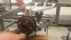
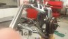
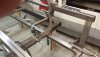
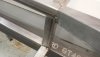
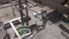
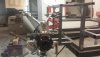
Cutting the compound angles then Jig it up before tack weld. 123 Block are precision ground and are cheap to buy.Mock up of suspension, do i have it backwards ? I need to make sure the compound angles are correct before welding.
Milling the compound angle (upside down photo??) Then Jig it up with 123 Blocks and check all dims square, parallel, level. a little tapping nudging here and there get it perfect for tack weldingStarting the welding jig squared up ends on the Hass using XYZ to make measurement. View attachment 106163
Attachments


Fantastic advice from you guys i will start at 5 degrees and figure out the thickness of the washers,Thank you!Start with setting the upper control arm to the frame with 5 deg or so. Doing that will allow you to use the least amount of shim stock necessary keeping in mind that you may want to use shims in the same spots to adjust camber.
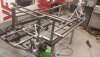
Hi Eddy, added shims to change caster. Used two ball bearings hung from thread and super glued to the top ballpoint to find center. I think this give some adjustment ?I was talking about caster angle...the upper balljoint being slightly rearward of the lower balljoint...giving some steering stability and self-centering effect. One way to make this adjustable would be to make provision for spacers here:-
View attachment 107167
To allow for the upper arm to be moved rearwards to add caster.
Attachments
Ed McClements
Supporter
Looking good - what does that give you? I think you want to start at 5 degrees, and have the ability to add a little more caster (so you have a range of 5 to 10 degrees) rather than removing caster (giving you 5 to zero degrees). These cars are light on the front-end.
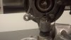
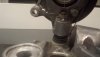
That is the rear suspension using a shop protractor I get 3 degrees plus what ever the cam on C5 lower has if that is how it works ???? Getting the front suspension this week. Thanks for the shim advice.Looking good - what does that give you? I think you want to start at 5 degrees, and have the ability to add a little more caster (so you have a range of 5 to 10 degrees) rather than removing caster (giving you 5 to zero degrees). These cars are light on the front-end.
Ed McClements
Supporter
Sorry - I thought that the steel tie rod was a steering arm, and that I was looking at the front suspension.
Good afternoon, working on front suspension and the C5 has four bolts upper arm. Washers would work on the lowers if I set caster 5 degree positive and had washers to get up to 10 degrees positive. Do you think that would work???Sorry - I thought that the steel tie rod was a steering arm, and that I was looking at the front suspension.
Working on chassis considering suspension with adjustable compression rebound damping shocks, modifying them to get a light coil maybe 350 lbs then using nitrogen for final ride. I got 20 bodies ready to be machined into shorter lengths.
[/QUOTE So I am at about 60 hours into the build trying to figure how the front suspension goes I think we need to be at 95 inches from rear center to front center I think the hubs need to be even with the rear hubs I think there should be 5 to 10 degrees positive caster adjustable with shims. I probably should have not watched Ford V Ferrari.
Attachments
Similar threads
- Replies
- 7
- Views
- 1K