Bill Kearley
Supporter
Just another note. When setting up your control arms, Have them at ride height !!!

Thanks for that will do, waiting for the body sections should be here soon.Just another note. When setting up your control arms, Have them at ride height !!!
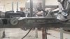
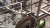
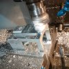
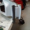
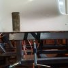
Good morning Bill I am following your advice and hoping I am doing it right. Front C5 suspension See level to bottom of frame. the steel under lower arm is there to support it for now. See 123 block temporary shaft welded so to move lower arm forward rear ward (to make sure it fits body) I measured 6 degrees positive caster. 123 block holding upper arm. About the 123 blocks they make this so easy they are 1 inch thick 3 inches long and 3 inches wide perfectly square and are cheap we use the in our CNC mills. Bill let me know thanks for all the adviceJust another note. When setting up your control arms, Have them at ride height !!!
Hi Edddy I posted some more on the front suspension last post page 3Sorry - I thought that the steel tie rod was a steering arm, and that I was looking at the front suspension.
")
Go to eBay type 123 block about $8.00 each. We use them on our CNC mills to position parts for machining, Works great on the chassis buildAllan, you have a very rare set of 123 blocks. I have never seen any that are 1” thick, 3” wide, 3” long.
Keep up the good work
Regards Brian
You are right,Too much coffee ebay has them cheap 123 block GT 40 blocksI realize that as I am a machinist also. The point I was remarking about is a 123 block is 1" thick, 2"wide, and 3" long.
" About the 123 blocks they make this so easy they are 1 inch thick 3 inches long and 3 inches wide perfectly square and are cheap we use the in our CNC mills."
Not 1" thick, 3" wide, and 3" long.
Sorry you didn't see the humor in your post as I read it.
Regards Brian
Just another note. When setting up your control arms, Have them at ride height !!!
[/QUOTE Good afternoon Bill
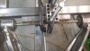
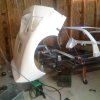
Doing the front C5 suspension mock up using shims on bottom control arms to go from 5 degree +caster to 10 degree + caster. when doing that center-line of rear to front axles changes, so I added 4 more hole on the upper to move center line back to 95 inches. The body should be done in a few weeks. What do you think???
And thanks for that Mark. Appreciate all the advice. Car is a lot of fun to build, going together faster than I thought.Allan, great build, interesting follow. Caster is a somewhat counter intuitive thing; your steering axis leans back (relative to direction of motion) at the top to provide caster. Thanks for the posts! -Mark
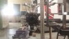
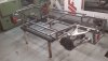
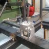
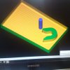
All most done with chassis, waiting for body to arrive if it looks good then it gets disassembled, and Tig welded.Starting the welding jig squared up ends on the Hass using XYZ to make measurement. View attachment 106163
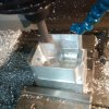
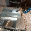
Built the 996 shift box today out of hog out, used a 996 plastic box and made measurements to do a program on the CNC millStarting the welding jig squared up ends on the Hass using XYZ to make measurement. View attachment 106163
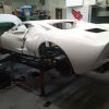
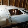
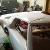
Ten weeks into the build, body arrived today if it looks good then time to tig weld. Time so far about 80 hours.Starting the welding jig squared up ends on the Hass using XYZ to make measurement. View attachment 106163
No not really north. It would be 3/4" right of the car. Got to make the aluminium parts another time. But the CNC is set up for more parts. Got to make a small change and move the boss. Then it wont hit the fiberglass. Thank youIs north towards the front of the car?
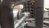
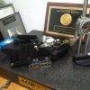
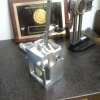
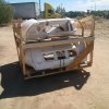
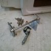
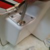
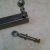
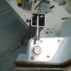
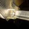
Out with the old in with the new (scrapped old design). New Door hinge. Clears the body and the door opens all the way. I cut from 17-4 stainless an adjustable shaft that turns in or out without removing rod end each time. It goes thru frame steel that is slotted to move door forward backward and fine adjusted with a 1/4-24 set screw. A 10.500 inch 7/16 stainless rod with 2.00 inch of 7/16 X 20 thread at both ends give up and down adjustment. When proper height is found then i will cut spacers will be added and lock nuts will hold door solid. I made some mounts for the Clam shell out of aluminium cut the shape in computer model. Clamping the Clam shell on the frame with paint stirring sticks as spacers to simulate pontoon thickness and aluminium sheet. (And it matters as i made that mistake). Anyway checked the radius for the tires. Then checked the edge of hubs for equal distance each side.Having fun with the GT 40 made the door hardware. Got it wrong, need to move the pivot point as the door will not fully open. Maybe 3/4 inch north. Used drywall screws to jig the body parts together and get the lines close. I guess I will get some body panel glue and mix it. They say 50 min till it cures. And it can be reversed with heat. The drywall screws make small holes that hopefully can be filled. About 120 hours so far in to the build.