Ammeter ? for Doc Watson (ANDY)

Doc Watson

Lifetime Supporter
Ok its officially Wednesday here in Blighty....

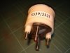
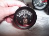
My ammeter has the same seriel number as yours... 5539-233T it came from ex-military stock off a Land-Rover series II which has a 12v -ve earth supply.

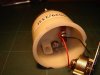
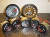
The following photos show disassembly and possible locations for an iluminating bulb.

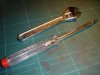
You will need a thin shaft screwdriver and an adjustable wrench.

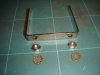
1) Remove the mounting bar nuts and lock washers and slide the bar free
2) I then removed the nuts on the +ve and -ve connection threads (later I realised you do not need to do this)
3) I then very carefully prised the 3 tabs on the bezel (the black metal rim that holds the glass on) so they were near straight
4) Very carefully rotate the bezel so that the 3 tags line up with the 3 'notches' in the plastic casing
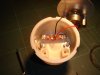
5) Gently pull off the bezel, be careful as the glass is free to drop out
6) Remove the glass disc and rubber 'gasket'
7) Look at the rear of the gauge and you will see 2 small recessed screws, these actually hold the working part of the gauge to the plastic
8) Hold the ammeter upright (you dont want the innards to fall out) and remove both screws
9) Gently place a finger and thumb either side of the needle of the gauge and tip the gauge and the innards will slide free. Do not force it out and remember that the needle is VERY delicate, snap that and its game over
10) I then held the dial and ammeter workings by the rim of the gauge and slowly pulled the ammeter free from the casing, there are wires attached which will only just allow the gauge to be removed.

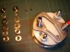
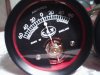
I took a series of photos for you and from the look of the plastic and the ammeter workings I think the best position for the bulb would be located on the back face of the plastic housing right in the centre. The bulb will not be inserted to far into the hole created and a sutible bulb holder will have to be found/made.

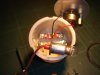
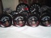
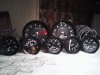
The internal surface of the gauge will be painted matt red and can be done in a disassembled state with a steady hand, working in stages around the wiring. Drilling the rear hole will be fun and will probably be done by hand. You will need to watch out for the internal wires that connect the ammeter to the external terminals. I took a photo of my oil gauge light with the ammeter to give you an idea of scale for the bulb. A thinner bulb might be better, need to look into that.

Also not that when I removed the connector nuts I noticed that the shunt plate had been soldered to the connection screws which prevents any further removal of those items, hence the note in point 2.

I then re-assembled the ammeter....its getting late here and I have done a 13 hour shift and thought it best to quit while I was ahead. When reassembling reverse the process again using exterme caution when replacing the ammeter and also be careful not to get the internal wires trapped in the seating location of the ammeter. It took me 3 or 4 attempts to get it seated correctly without the wires in the way so the small holding screws could be tightened.

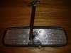
I also have a pic of my Lucas 608 mirror which is having a replica mounting boss and stem produced for it. Its important to remove the mirror glass before replacing the stem!. Jay Cushman of Cushman Comp is producing it for me and has supplied me with a few other pieces. The quality of his stuff is superb, I have no kickbacks or affiliation with Jay, I'm just a very happy customer. His web site is below, and his list of replica parts is growing.

GT 40 Parts

The mirror will be fixed to the windscreen glass with clear epoxy.

Hope this info helps.

Andy
 

Attachments

  • ammeter 001s.jpg
    ammeter 001s.jpg
    59.6 KB · Views: 384
  • ammeter 002s.jpg
    ammeter 002s.jpg
    55.7 KB · Views: 360
  • ammeter 004s.jpg
    ammeter 004s.jpg
    42.6 KB · Views: 393
  • ammeter 005s.jpg
    ammeter 005s.jpg
    54.2 KB · Views: 425
  • ammeter 006s.jpg
    ammeter 006s.jpg
    39.4 KB · Views: 409
  • ammeter 007s.jpg
    ammeter 007s.jpg
    43.1 KB · Views: 396
  • ammeter 008s.jpg
    ammeter 008s.jpg
    37.7 KB · Views: 431
  • Lucas 608s.jpg
    Lucas 608s.jpg
    50.2 KB · Views: 398

Steve C

Steve
GT40s Supporter
Andy,

Thanks!

Good to know the meter is 12V (was thinking I might need to rewind the meter movement resistor if 24V to achieve proper scale readings).

That CAV sure is well built as compared to newer ammeters.

If bulb is installed from the rear would be in center of the shunt and exposed to heat from the shunt (problem if a plastic bulb socket?); also wheras the socket will be grounded it could vibrate loose and short against the shunt if metal.

Hard to tell from pics but, also looks as though the rear of the meter movement would be very close to bulb?

What about mounting the socket through the top of the case...looks as though there is room there?

Re mirror...Now I understand.

Thanks again.

Regards, Steve
 

Steve C

Steve
GT40s Supporter
Andy,

More on the CAV ammeter :

Meter arrived and is marked same as yours (5339/233T) and outwardly exactlly same...But, mine has a fixed resister instead of the wound resistor board and red lead like yours (serves same purpose but must be a later build redesigned for simpler manufacturing).

I'm thinking of using a red magic marker to red up the interior (seems all that is needed is to colour in from the face a few inches at the bottom and an inch or so at the top).

For illumination I think best to come in the side of the case at about 2 O clock...Thinking about a plastic bulb socket with an interferance fit into a rubber grommet (shouldered on both sides to fit into and lock into the hole drilled in the case). Maybe glueing 2minimum shouldered plastic collars (spaced to lock the socket into the grommet). Small bulb with a red bulb condom if further white light reduction needed.

To mock the useful plastic screw through the face glass that allows meter movement needel centering I'm thinking of having a mirror shop drill a hole in the gauge glass and self threading a black plastic bolt into the hole.

What do you think?

I feel much better about using this ammeter (It's a quality unit...well built industrial design with large shunt and screw studs vs the quick disconnect terminals on the 50 A gauge that came with my car...Seem to be a number on ebay UK from time to time ...Good upgrade and thanks again for you help.

Steve P2125
 

Charlie Farley

Supporter
Andy et al

Just finished refurbishing CAV Ammeters.
New black bezels and red interiors.
Thought you might be interested.
 

Attachments

  • CAV Ammeter1.jpg
    CAV Ammeter1.jpg
    47.3 KB · Views: 392
  • CAV Ammeter2.jpg
    CAV Ammeter2.jpg
    35 KB · Views: 419
  • CAV Ammeter Cluster1.jpg
    CAV Ammeter Cluster1.jpg
    39.6 KB · Views: 449
  • Cluster 1.jpg
    Cluster 1.jpg
    41 KB · Views: 401

Steve C

Steve
GT40s Supporter
Andy (Charlie Farley),

Nice job on the CAV's...What did you use to red up the case inside?....Did you illuminate and if so how?...I've been trying to decide to add the hole and plastic screw plug to front of gauge glass as the originals but, all the glass companies here are cautioning me to not drill the needed hole as I will likely crack the glass (wonder how CAV did it originally) Suspect reason for the black slotted screw was to allow "meter zeroing? ...Do you know answer to either question?

Did you do anything to the other gauges?

Thanks, Steve
 
Last edited:

Charlie Farley

Supporter
Hi Steve,

I used scarlet coloured paint and a brush. Spraying was too awkward.
I have a period correct original 40 CAV Ammeter with the black adjustment screw.
You are correct, the black scew is used to zero the gauge. You will notice, there are differences between the gauge face of a period correct Ammeter and the Ammeter shown in the photos, in terms of position of screws holding the faceplate on, font and
scale layout. But hell, the ones we are talking about are close enough for me.
The remaining gauges, Speedo, Tacho, Fuel Gauges, Oil, Water etc,
are part of a batch i had remanufactured for myself and a few friends.
 

Doc Watson

Lifetime Supporter
Hi Andy,

Gauges look very nice... do you have a supplier for the black bezels?

How is the build coming along?

Andy
 
Steve, if you check out post No 5, you will see that your numbers are the same as Docs. Therefore you should be OK, or you are both in the same boat!!

OK so I am late,as usual. disregard this post.
 
Last edited:
I did edit the above post when I realised I was way behind the posts, did'nt realize there was a second page!! DUH! But it did not work, so I,m not really stupid!! I think!
 

Trevor Booth

Lifetime Supporter
Supporter
Doc,
I have looked thru some old CAV-Lucas catalogues and it appears that the CAV ammeter was either not illuminated or had slots around the case and an external bracket for holding the globe holder. The slots around the case were covered with thin acrylic sheet to prevent stuff getting into the gauge. I do not know what original cars had but would suggest they probably had an external bracket to hold the globe holder. The external globe holder does not have the problem of extraneous light shining thru the face. I have a NOS bracket that i could dimension if of assistance. The bracket does not in itself hold the globe. A globe holder the same as what fits into other instruments mounts in the bracket and takes the same miniature globe.
 

HILLY

Supporter
Hi Doc,
Have you had any progress with the plastic 'chinese hats'.
I have not had a chance to do anything with them to date but will have to look at getting something done shortly and would be interested to see how your forming method works rather than trying to machine them.
 

Doc Watson

Lifetime Supporter
Peter,
No progress so far on this but I was planning to use a wooden female mould (maybe metal if I can get someone to turn it correctly, then heating up some plastic and then push it into the mould, alternatively I might use epoxy and 'pour' the hats which will allow me to use non metal mould.

Trevor,
I think illumination was discussed before, I plan to drill a hole in the plastic casing and use a 'standard' light bulb and holder. The light bulb will be 'painted' using a permanent red marker pen to give the red glow. Also the inside of the ammeter will need to be painted red. Picture ammeter008s.jpg earlier shows the bulb and holder.

Andy
 

JimmyMac

Lifetime Supporter
Charlie Farley and Doc,

Give it a rest here as people are believing that you supply or know all about original gauges.
Have you ever thought that you are on the wrong track completely with these mock-ups and need time out to detach your imaginative model making skills from car building?

Clarification for the rest of us:
On original gauges (see photo), the tacho was the only gauge to be painted red inside and the CAV ammeter had only the original white opaque illumination ring painted with red stage light paint. Light was provided by standard Lucas clear bulbs.
All other gauges in the set had red illumination filters and not red painted shells.

The indicators were one piece in manufacture to a large hub design. Later cars or refitted gauges did not necessarily have the the original style indicators.

If you must go for red bulbs and fake indicators search the market and you will find them.
 

Attachments

  • Gauges.jpg
    Gauges.jpg
    241.8 KB · Views: 322
  • Gauge Fittings.jpg
    Gauge Fittings.jpg
    215.5 KB · Views: 306
Last edited:
Back
Top