
You are using an out of date browser. It may not display this or other websites correctly.
You should upgrade or use an alternative browser.
You should upgrade or use an alternative browser.
Bundle of Snakes Clearance Issue
- Thread starter Ragtime Kid
- Start date
I have the same problem with my exhaust as well on my RCR and my next step was to add the washers as you suggested. Will let you guys know the outcome when I get my straight pipes back from being welded.I think I would put a couple washers between the block and motor mount on both sides to see if that would buy you the needed clearance..
Bill Kearley
Supporter
I half expect that raising the engine will only rotate the pipes to the rear and not have any effect.
Will an RCR be able to accept a new mount under the gearbox ? Build one to suit !!
Will an RCR be able to accept a new mount under the gearbox ? Build one to suit !!
I half expect that raising the engine will only rotate the pipes to the rear and not have any effect.
Will an RCR be able to accept a new mount under the gearbox ? Build one to suit !!
Good point just made me realize that adding the washers between the block and the motor mounts will just misalign the ZF gearbox dog ear mounts and the cross-support brace. On an RCR chassis you have the 2 holes in the upper support that accept 2 bolts through the dog ears of the gearbox upper mounting plate. Not much wiggle room. I do have 2 mounting tabs with bushings on the bottom of the bellhousing which line up well with the cradle of the chassis, I just need to fabricate and weld L type brackets with bushings for through bolts to complete the motor mounting process. The problem is in the design of the bundle of snakes supplied by RCR. I believe the solution (if any) should probably be within the bundle of snakes. Just need to gain a 1/8-3/16" gap between snakes and chassis support.I half expect that raising the engine will only rotate the pipes to the rear and not have any effect.
Will an RCR be able to accept a new mount under the gearbox ? Build one to suit !!
Attachments
In addition to the rotation you mentioned, It will also lift the pipes up the amount that you shimmed. I have already played with this on my own car. Yes, there will be a slight misalignment with the transaxle support, but you may have enough compliance in the bushings. If not - well modifications are in order..I half expect that raising the engine will only rotate the pipes to the rear and not have any effect.
Will an RCR be able to accept a new mount under the gearbox ? Build one to suit !!
—
Frankly speaking, there is a LOT of material in the RCR dog bone and I wouldn’t be afraid of milling some material off of it to clear the headers.
Hi Vinny
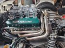
Those a great looking set of headers and very well made. The clearance solution is in the headers OR the cylinder heads (or block deck height).
We ran into issues with CAV SA supplied headers for small block Ford 302s. The engine was from Ford Racing, 347 with "Z" heads. The problem was not clearance to the ZF transaxle mount, rather the tubes wouldn't line up with the collectors. It became apparent the Ford Racing Z heads were raised port - moving the pipes farther apart. I took about 17 sections to fix the issue. No fun at all and not really a mistake at the factory.
Your situation is the same except you are going up rather than out. Same fix, the pipes will have to be cut and additional tube pies or sleeves welded in.
However, there is a bright side to this, you can now move your exhaust gas oxygen sensor to a pipe forward of the collectors. This prevents the sensor from reading air entering at the collectors. This usually results in a false air fuel mixture being sent to the fuel injection or engine control unit.
Beautiful car btw, carry on")
Ian
Those a great looking set of headers and very well made. The clearance solution is in the headers OR the cylinder heads (or block deck height).
We ran into issues with CAV SA supplied headers for small block Ford 302s. The engine was from Ford Racing, 347 with "Z" heads. The problem was not clearance to the ZF transaxle mount, rather the tubes wouldn't line up with the collectors. It became apparent the Ford Racing Z heads were raised port - moving the pipes farther apart. I took about 17 sections to fix the issue. No fun at all and not really a mistake at the factory.
Your situation is the same except you are going up rather than out. Same fix, the pipes will have to be cut and additional tube pies or sleeves welded in.
However, there is a bright side to this, you can now move your exhaust gas oxygen sensor to a pipe forward of the collectors. This prevents the sensor from reading air entering at the collectors. This usually results in a false air fuel mixture being sent to the fuel injection or engine control unit.
Beautiful car btw, carry on
Ian
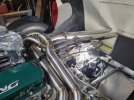
Thank you. Actually, there are 5 issues with these snakes. I had to remove material from the head flanges to make room for spark plug and wire removal. The snakes are very close to my fuel supply and return lines. Very close to the underside of the deck, and also are barely touching the dog bone. Collectors do not receive the pipes well, causing problems with exhaust leakage. Collectors were supplied with tabs on the outer sides but not on the inner sides between the 2 collectors. Even with the use of copper RTV silicone still leaked. I had ordered 8 new tabs to weld onto the pipes and collectors to pull pipes and collectors tighter.
I am thinking if I need to modify these headers as much as you are suggesting I am probably better off having new snakes made up for my application. These may look good but if I start cutting into them and adding pipe, then not so much!
I am thinking if I need to modify these headers as much as you are suggesting I am probably better off having new snakes made up for my application. These may look good but if I start cutting into them and adding pipe, then not so much!
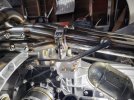
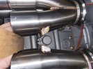
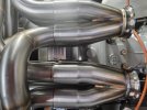
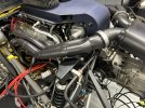
I am using the same set up on my RCR and am having issues with leakage between the pipes and collectors. I tried several times using copper sealant and still leaked slightly. Got tired of reinstalling these headers. I finally purchased 8 more of the tabs and am having a fabricator weld them on the inner side pipes and collectors (between the two banks) so I can pull all 8 pipes in fully to the collector flanges. I think that will limit any movement between them and along with sealant It should work. It is going to be a tight fit but I think that is my only solution. Did you have any issues with exhaust leakage? I am also very close to the dog bone with my headers. (I reversed the collectors in photo 2 to show how close the tabs are. I think with modification, or offsetting them, it should work)So my exhaust headers just barely clear the crossmember. In fact, one of them is ever so lightly resting on it and the other has a tiny clearance (maybe 1/32"). You can see in the pix that the part that is interfering is the "thinner" diameter and where the collector slips over the header tubes is just touching the outside edge of the crossmember.
Would it be a good idea to put something in between there to reduce the likelihood of the pipes wearing through? I thought perhaps a strip of heat shield fabric (the kind that is woven ceramic with a silver coating on one side)? Or even thin strip of pine door shim? The idea being that the middle layer of the sandwich would wear before the pipes. The other side of doing that is that it puts more pressure on the pipes which, for now or not under much if any force resting there (at least not when cold).
I've got about 500 miles on the car so far with it this way and so far it doesn't seem to be an issue. I also can't tell if there is any movement back there between the Prothane engine mounts and the stiff bushing holding the ZF in place.
Any thoughts/suggestions?
Attachments
If those are "single slip" connections to the collectors, you'll likely always be challenged in getting them to seal. You need double slip connections and even then they sometimes leak enough to cause O2 sensor misreading. I've been surprised on one of my cars on how challenging it is to keep the outside air from sneaking into the exhaust and causing the EFI to run rich. I'm in the process of moving the O2 sensor upstream now as I just can't stop a V band connection from leaking air in.
Thanks for the feedback. I had a feeling that the leakage would be a general issue with other builders. I had them sealed and then tested them again a few days later and they leaked just slightly. I think stabilizing all the pipes with the tabs and sealing them should do the trick. We will see. I'll keep you posted.If those are "single slip" connections to the collectors, you'll likely always be challenged in getting them to seal. You need double slip connections and even then they sometimes leak enough to cause O2 sensor misreading. I've been surprised on one of my cars on how challenging it is to keep the outside air from sneaking into the exhaust and causing the EFI to run rich. I'm in the process of moving the O2 sensor upstream now as I just can't stop a V band connection from leaking air in.
It's coming up on twenty years since we did our first 8 stack EFI system. This was before self learning software was available. However it was possible to manually adjust the tables to improve the tune and lock it in.
Tuning was real expensive back then, a lot of time on the rolling road dyno between road tests.
Fortunately self learning software has greatly simplified the tuning, although the mechanical aspects still have to be correct.
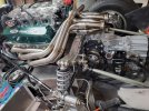
I have yet to see a completely sealed bundle of snakes exhaust system accomplished without welding up the complete system. Not a good idea from a heat expansion or serviceability point of view in the GT40 application.
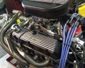
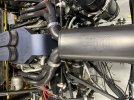
Picture below shows where we relocated the EGO sensor to a front pipe to get away from the collector. It's probably the best and simplest solution for the GT40.
Cheers
Ian
Tuning was real expensive back then, a lot of time on the rolling road dyno between road tests.
Fortunately self learning software has greatly simplified the tuning, although the mechanical aspects still have to be correct.
I have yet to see a completely sealed bundle of snakes exhaust system accomplished without welding up the complete system. Not a good idea from a heat expansion or serviceability point of view in the GT40 application.
Picture below shows where we relocated the EGO sensor to a front pipe to get away from the collector. It's probably the best and simplest solution for the GT40.
Cheers
Ian
Attachments
Hi Vinny
That is true unless you have leaks going into the collectors. We're dealing with slip collectors here.
The same goes with a four into one header (four cylinder) or either side of a V8 side pipe (Cobra etc).
If your header collector leaks you must go up the pipe to get a proper sensor reading.
Also applies if you are too close to end of the exhaust pipe.
Hope this helps
Cheers
Ian
When you're on one primary, you're only reading the one cylinder. If everything is right and fuel is equally distributed, that's fine. I wouldn't try to run closed loop like that, but for tuning, verify that the plugs look the same and lock it in, it'll work 95%.
The thing you need to know is how the sensor works. It gives a calculated AFR based on tiny trace amounts of unused O2. The tiniest leak, or misfire gives a hugely lean reading. Even if it's a misfire because its super pig rich. Bear this in mind before you abandon all senses and put all faith in the sensor.
I don't run the Cobra closed loop for this reason. I use the AFR gauge more as an exhaust leak indicator.
Sounds like a good idea if you are adding washers to the mounts.Thinking about this for a day, when I get to the shop, I’ll see what I can do about building a couple offset bushings for the transmission / upper cross member, all the 40s I’ve worked on had the steel x member and there were no clearance issue , I’ll keep you posted
Thats a thought not much material to remove, I'm thinking just enough material just by removing the RCR logo should do it!In addition to the rotation you mentioned, It will also lift the pipes up the amount that you shimmed. I have already played with this on my own car. Yes, there will be a slight misalignment with the transaxle support, but you may have enough compliance in the bushings. If not - well modifications are in order..
—
Frankly speaking, there is a LOT of material in the RCR dog bone and I wouldn’t be afraid of milling some material off of it to clear the headers.
Thanks for the feedback. I had a feeling that the leakage would be a general issue with other builders. I had them sealed and then tested them again a few days later and they leaked just slightly. I think stabilizing all the pipes with the tabs and sealing them should do the trick. We will see. I'll keep you posted.
I suspect that material expansion, especially stainless steel, is a factor that we underestimate and then it surprises us. So a test for leaks in exhaust system done at 70 degrees F is not a valid test. I think you'd need to test for leaks at the normal to higher operating temperatures of the exhaust system to have a valid test.
I also was originally thinking because the pressure should be higher inside the exhaust than outside that it would leak outward instead of inward. I suspect the exhaust pulses create more "momentary" vacuum than we think will be present in the pipes and this vacuum pulls the outside air in. In the car I'm about to relocate the O2 sensor on, I can feel the engine start to surge/run rough about 3,400 rpm and up. Sometimes there's a popping sound in the exhaust which I believe is unburnt fuel that is detonating in the exhaust pipe. I believe it's at the higher rpm levels that air is leaking into the pipe, O2 sensor is fooled and EFI starts dumping in way too much fuel. Below that rpm level the engine runs fine.
Hi Joel,
There are threads on the forum detailing how to set up the throttle linkage for 4) Weber 48IDA intake systems. There's also information about choosing emulsion tubes and jets that do not apply to EFI systems. Those threads are worth reading regardless if you have an individual runner EFI system or Webers.
What absolutely applies to an eight stack EFI system is the synchronization of the throttle blades at idle and as the throttle is opened. If you are not synchronized then each cylinder will not receive the same volume of air per intake stroke. This upsets the air fuel ratio per cylinder, some may be right on or lean or rich. Make sure the throttles open equally.
Also verify that both banks of throttles open equally. We had one EFI system that would not pull open the paired throttle bodies equally even though the linkage arms, throttle stops and levers were all the same. It turned out the central pivot the throttle cable pulls on was slightly offset to one side on the intake manifold mounting pad...
Then you can consider other factors such as ignition timing, advance curves, fuel pressure, injector size and bandwidth and injector timing. Get all that right and the intake side should be ok.
Then you're back to the quality of the EGO sensor signal and it's best location to avoid air leaking in resulting in a bad reading at the sensor.
Cheers
Ian
Similar threads
- Replies
- 2
- Views
- 894
- Replies
- 20
- Views
- 3K
- Replies
- 3
- Views
- 978
- Replies
- 8
- Views
- 2K