Camber advice please ( RCR40 ).

I'm having some trouble setting up the camber on the front after replacing the Heim joints & ball joints.
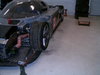
The car is up on stands at present, no wheels or hubs.
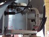
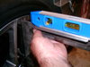
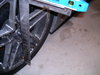
From what I have read you level the lower control arm then measure the angle between this and the face of the steering knuckle.
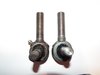
The two lower Heims are half way out , the two uppers and the upper ball joint are screwed all the way in, I make the angle to be 0° at these settings.
I can't see how I can get -1° without the lower two Heims screwed a long way out.
Also the new upper ball joints have a shorter threaded length , so will not screw in as far.
Before, the two lowers had a couple of threads showing and the uppers were screwed all the way in but I don't know what the angle was.

Any advice much appreciated, thanks.
 

Attachments

  • Camber angle.JPG
    Camber angle.JPG
    75.7 KB · Views: 464
  • upper ball joints.jpg
    upper ball joints.jpg
    47.7 KB · Views: 448
I have cut more threads on the chevy tie rod / upper ball joint to allow it to seat completely in the upper control arm this will give you more depth, I have seen quite a difference depending on manufacture on the threads. The set up goes negative camber very quickly from that level set up with such a short upper control arm.
 

Neil

Supporter
Cutting more threads on a rod end bearing or even a bolt is not a good idea. The original threads are rolled, which generates the proper grain structure in the steel. Cut threads have less strength, particularly in fatigue. Not good.
 
It sounds like you are trying to adjust the car on jackstands. If so, I'm surprised no one has mentioned this- you set suspension with the car on the ground. Put the wheels on and set it up that way. Trying to set camber with the suspension at full droop is a waste of time- static camber (and toe, and everything else) needs to be set at the ride height the car will run.

My guess is that when you do that, you'll find that the existing rod ends have plenty of adjustment.
 
Correct Will, set the car on the groung give it a good bounce to settle things, and then do your thing, and may i recommend a cheap digital angle meter and a level or straight edge on the outside of the wheel, and set it at 1-2 deg neg
cheers John
 
I am not sure I agree Neil we have certainly made parts with the Bridgeport mill and also used the lathe for threading of pieces as well as using taps and dies to cut when needed and I don't recall any failures yet........ respectfully..........................................Mahlon.......millermotorsports
 

Neil

Supporter
Mahlon;

Threads that are roll-formed after heat-treatment are stronger but, more important, they have higher fatigue resistance than cut threads. That is not to say that you can't cut threads on a bolt and have it work perfectly well. It depends on the stress level in the fastener. An appropriate small highly-stressed bolt with rolled threads could be replaced by a larger bolt with cut threads because its stress level is lower.... and it would work just fine.

http://www.atlrod.com/products/advantages-of-rolled-threads/
 

Randy V

Moderator-Admin
Staff member
Admin
Lifetime Supporter
On mine, I had to remove the outer nut on the upper balljoint. Since the upper control arm is threaded, the outer nut served only as a jam nut and I don’t believe it is required to have two jam nuts...
you might find some pictures on my old build threads or my build blog (link below)..
 

Howard Jones

Supporter
YOU CAN'T DO IT THAT WAY. The car needs to be sitting on it's weight with it tires and every thing else on it. I would put a weight in the driver seat to approximate your weight also. If you intend to carry a passenger more than 50% of the time then add about 1/2 that weight to the passenger side. Fill it with fuel, oil and water. For now set lower rod ends to about 25% of threads exposed. All the rest all the way in. Then:

1. tires to normal cold pressures
2. set ride height
3. adjust camber to 0.
4. set toe front and back to desired setting.
5. reset camber F&R to final settings.
6. reset toe to final setting.

Do not expose more than 1/2 of rod ends at any location. If you need the lower rod ends all the way in then redo them. Why not start that way? So that you will have some adjustability left at the bottom and so that you can have max adjustability at top in the neg. direction.

Use the sidewall of the tire as your vertical plane for camber and horizontal plane for toe. The tire's contact with the road is what you are setting. Make measurements all the way across the center of the tire sidewall and through the centerline of the hub.

Here's a good 90% road car start point for settings:

Ride height = F 4", R 4.5"
Camber= F -.5 degree, R - .5 degree
Toe = F 1/16 " toe in each side. R = as close to 0 as you can measure each side. (about a 1/32 is as good as a tape measure gets) Be sure it does not go positive throughout the travel of the tire in compression and rebound.
Shocks = start at the center of the settings. If the shock has 10 clicks then set to 5. Shocks do not really effect alinement process but I include to be complete.

Have fun, give yourself a full day, and keep hydrated.
 
Last edited:

Bill Kearley

Supporter
If you can, lift the car off the floor and level, remove the wheels, shocks and springs. Get a good angle finder. set each hub at ride height with turn buckles in place of the shocks ( easy to adjust ) and adjust your camber,caster and toe.
 
Alright , so it looks like the only way to do it is assemble it , put the wheels back on , set it down on level ground then measure the camber/toe .
If it needs adjusting , jack it up , take the wheels off , pull the lower wishbone out , turn the Rose joints in or out, reassemble , repeat many times until happy with the setting.
Thanks everyone for your advice.
 

Bill Kearley

Supporter
No, reread post # 11, it' not that much work. Find an electronic angle gauge and a small laser ( there not expensive ). Jack it up and work of the rotor face for camber and toe with angle gauge. The toe can made spot on making reference points on the floor and a wall in front of the car. For the caster you will need a line from the lower to the upper ball joints to work from. For example the billit uprights on a CAV have perpendicular surfaces to work from.
 

Howard Jones

Supporter
You can measure camber angle with a 90 degree carpenters square, bubble level, and 6 inch pocket rule, and a bit of trig. Place the square against the wheel lips vertically with the 90 at the top sticking out away from the wheel and centered on the wheel so that the long arm of the square is straight up and down, place the bubble level on top of the short arm and correct the square out away from the wheel at the top with the bottom end against the wheel.

When the bubble is level measure the distance from the corner of the square to the wheel. You should have about a 1/4 of a inch gap for a 18 inch wheel and about a 3/4 degree of neg camber. You can make a chart for multiple degree angles and distance from the rim. From then all you need is the car on the more or less level ground, your camber stuff, and your chart.

something like this:
18
1/8 = .39
1/4 = .79
3/8 = 1.1
1/2 = 1.59

19
1/8 = .37
1/4 = .75
3/8 = 1.1
1/2 = 1.5

This will work for any wheel size or over all tire height if you like. I have a couple of cheap carpenter squares that I cut off the long arm to suit my wheel sizes. I welded a flat angle iron piece on the short arm to accommodate a magnetic bubble level. All in I have about 20 bucks invested.

See Trig calculator below.

https://www.rapidtables.com/calc/math/trigonometry-calculator.html

I'll post a pic when I get out in the garage.
 
Last edited:

Howard Jones

Supporter
Here are a couple of pictures of my homemade camber gauge. It's hard to hold and take pictures of at the same time. I just did a complete alinement of my SLC with the exception of caster. It can be done in a few hours with a string, a 6 inch rule, and my camber tools.
 

Attachments

  • HPIM2446.JPG
    HPIM2446.JPG
    736.1 KB · Views: 324
  • HPIM2447.JPG
    HPIM2447.JPG
    763 KB · Views: 298
  • HPIM2445.JPG
    HPIM2445.JPG
    769 KB · Views: 322
Last edited:

Ian Anderson

Lifetime Supporter
Download an app for your mobile phone that uses angles etc.i use one (free) on my I phone called Commander.

Ian
 
Back
Top