You might have noticed no pictures so far showing clecos. I finally broke down and ordered some, should have done so much earlier, they definitely make fitting up much easier.


You are using an out of date browser. It may not display this or other websites correctly.
You should upgrade or use an alternative browser.
You should upgrade or use an alternative browser.
CANAMSA - SA stratch build
- Thread starter Fred W B
- Start date
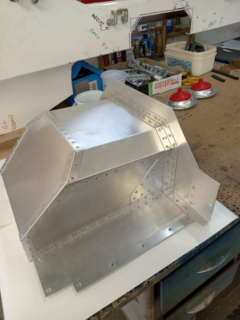
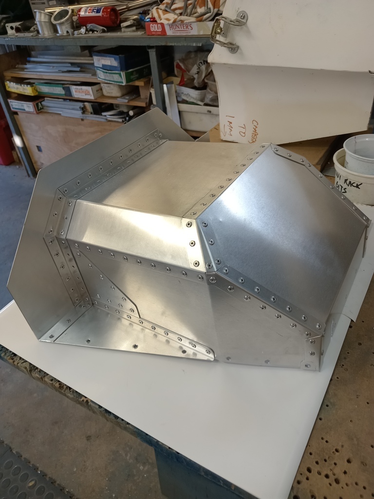
So now I had a center tunnel that contains the gearshift mechanism and the handbrake lever. I wanted a handbrake as my 7 does not have one at all and that’s a pain sometimes. The rear of this tunnel is open to the engine compartment.
To close off the top of it I made a pressing that goes under the handbrake. This bolts in again with m4 fasteners and I’m experimenting with some rubber strip to provide at least some sealing around the lever.
There is a separate closing plate over the gearshift mechanism. Still mockup gearlever shown, and I may still make a bezel for the gearstick hole.
Last edited:
And the final effect. I intend to eventually have some closed cell foam pads sewn into covers that will fit into the seats and be retained with press studs around the edges. I could also make an expanding foam seat insert for the driver.


Hi all, hope everyone had a good festive season and best wishes for the new year.
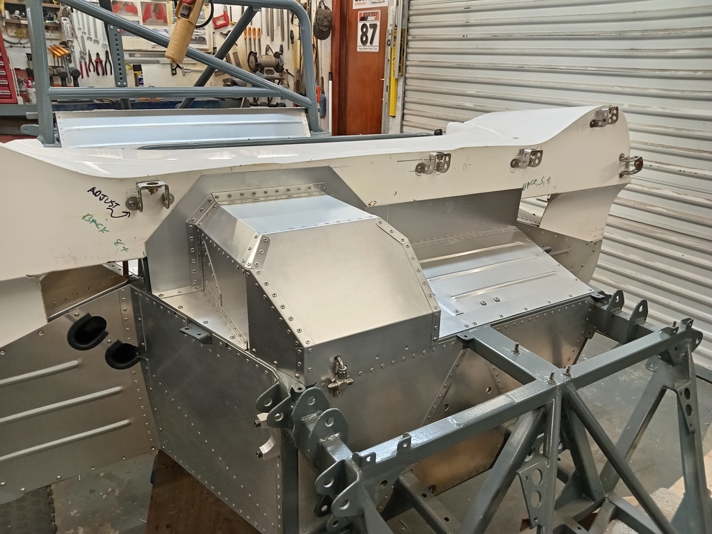
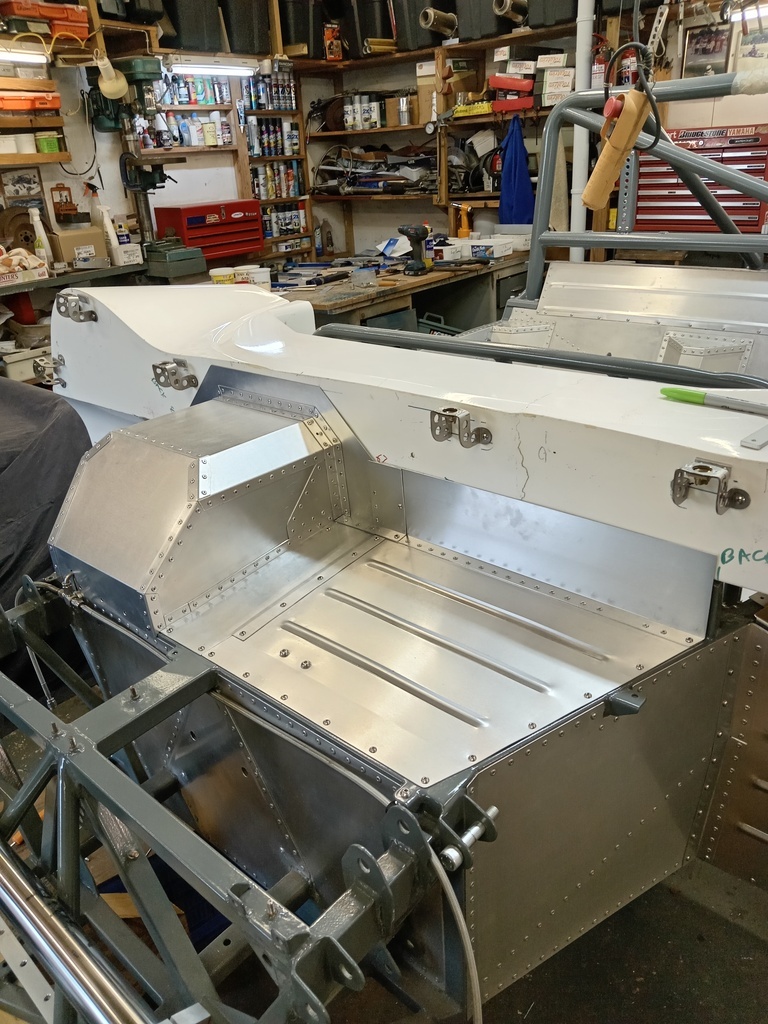
The next step was to panel the outer skins of the side pods. Very early on in the project I has tested the torsional rigidity of the mock up chassis both with and without riveted on side pods and that exercise convinced me of the benefit of making the side pods part of the structure. The original T70 has GRP sill covers over the outer edges of the monocoque but I thought to make the skins serve both purposes by making them so that they form the lower part of the body between the wheel arches.
I had made the chassis outer longitudinal side rails slightly narrower than the body width to give some ability to adjust the overall width to suit the body fit when I fitted the skins.
I spent quite some time positioning where the skins would sit to get them both dead parallel to and equidistant from the chassis center line.
I made a hammer form to bend a flange onto support ribs that would define the curve of the side pods. I agonized over whether to make this a consistent radius, or to make the skin first angle in more steeply below the belt line, as the original T70s appear to do. Eventually I decide to make a constant radius for simplicities sake. As the side pods are taller than they are wide this means that there is a 45 mm wide band of theoretically flat vertical surface at the top of the side pods which would prove problematic later on as I don’t have any stringers between the ribs. After the flanges were bent onto the ribs the flange width was trimmed to a uniform dimension.
I must state that I didn’t have any prior practical experience forming sheet metal beyond simple panel bending and folds. I’m figuring this out as I go along which is no doubt well apparent to the more accomplished metal workers.
The rear end of the pod is closed by a single panel, to which we added some stiffing detail. The top row of rivets is countersunk as they will be overhung by a flange on the removable top panel.
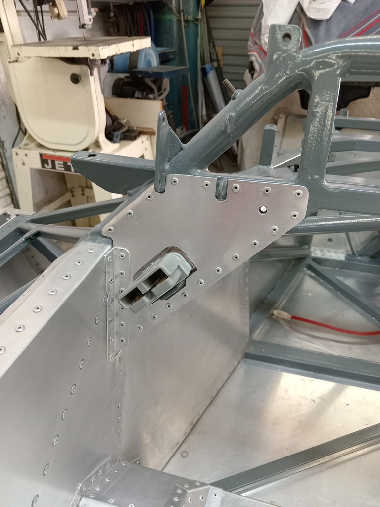
The front end of the pods have to have multi-piece closing panels, as the major part of them needs to be removable to enable the fuel tanks to be fitted into the side sills. On the driver side windows are needed in the ribs to accommodate pipes that transport the cooling fluid from the engine to the front mounted radiator. These pipes are supported in some brackets I had machined up. The accessibility once the skins are fitted needed to be considered. The ribs were carefully fitted to maintain a straight line down the length.
On the passenger side I put some holes in the ribs merely for the BS factor.
The skins were prepared with a folded flange at the top and the rivet holes drilled to meet the flanges of the ribs. Lacking access to a slip roller long enough to roll the curve into the skins in one operation we resorted to putting some shape into the skins by bending them on a bench with pipes, clamps, planks of wood and muscle.
The top of the skins was secured to the chassis with clecos. The skins were initially cut larger than necessary to enable battens to be screwed to the lower ends. I screwed some hooks into the battens so I could draw the lower ends together with ratchet straps and the skins would take the shape of the ribs. Once tight I drilled through the predrilled holes in the skins into the edges of the floor plate at the bottom and into the flanges on the ribs. I had let the floor plate overlap the lower frame members enough that the skins are riveted only though the floor material, and on the outer side of the floor. This with a view to making it easier to remove a skin later should damage repairs be necessary.
I then released the straps and removed the skins again to trim the excess material. Then refitted the skins now with countersunk rivets through the top flange, ensuring they were dead straight.
Last edited:
I then used the straps over an aluminum strongback to push the skin against the ribs at each rivet point, working from the top down.
At the front and rear ends the rivets are spaced at 20 mm over the whole length of the rib flanges. On the 4 intermediate ribs on each side I started the rivets at 100 mm down from the top, and spaced at 40 mm. I did this as I was worried that lots of rivets though the body of the skin would detract from the appearance, and I was aware that the upper theoretically flat part of the skin would in fact bulge outwards slightly due to the lower bend, as we were not able to get the pre bent radius exactly right. Rivets in this area might pull a small local dent in the skin again detracting from the appearance. I did get this effect at a few places, but I could remedy this by releasing the offending rivet and pushing a thin shim between the skin and the rib flange where necessary, before refitting a rivet through the shim. These were in the order of 0.5 mm thick at the outer ribs and up to 1.2 mm thick on the inner ribs.


At the front and rear ends the rivets are spaced at 20 mm over the whole length of the rib flanges. On the 4 intermediate ribs on each side I started the rivets at 100 mm down from the top, and spaced at 40 mm. I did this as I was worried that lots of rivets though the body of the skin would detract from the appearance, and I was aware that the upper theoretically flat part of the skin would in fact bulge outwards slightly due to the lower bend, as we were not able to get the pre bent radius exactly right. Rivets in this area might pull a small local dent in the skin again detracting from the appearance. I did get this effect at a few places, but I could remedy this by releasing the offending rivet and pushing a thin shim between the skin and the rib flange where necessary, before refitting a rivet through the shim. These were in the order of 0.5 mm thick at the outer ribs and up to 1.2 mm thick on the inner ribs.
This turned out to be quite a bit of a fiddle to get right, but eventually I was happy with the result, although I haven’t taken the protective film off yet!


Hi All
I have now entirely finished the aluminum paneling, save for some small filler pieces that can only be finalized one the body is finally fitted.
Having worked on cars that were apparently assembled with no regard for later access to some components for maintenance or repair I was determined to ensure good access . To that end the major parts of the side pod tops, the forward faces of the side pods and also the top of the cockpit section over your legs are all removable. The removable panels are secured by M4 button head cap screws. Threads are tapped into aluminum backing strips behind the ally panels, or into rivet nuts where the attachment is to a frame member.
The total mass added by the paneling and securing methods came to 53 kg (117 pounds) . Total number of M4 bolts is in the order of 300.
Ill do a couple of further posts with some more details.
I've seen some race cars where the driver was apparently happy to see the fuel tank from the driver's seat. I've got too much imagination for that, so the fuel tanks are positioned in the left and right side pods and completely covered. The fuel tanks are located with their centers on the longitudinal center of gravity of the car.

I decided the split the main side top panel in two, with the option to remove either end independently depending on which end of the main side pod you wish to access.

On the passenger side the rear lower section of the side pod alongside the engine will contain most of the fuel system parts.
On the driver side it is reserved for a future dry sump oil tank.
On the passenger side the forward section of the side pod is empty.
On the driver side an electric water pump (one of two on the car) will be fitted. This will be accessed though the panel on the front of the side pod, the panel has 2 holes for the water pipes to exit towards the front mounted radiator.

The foremost top panel, on the right is this picture, will be riveted to the chassis as it will have the body scuttle and door hinge support mounted on top of it. I have not riveted it yet as I still have to finalize the wiring harness securing / routing and this will be easier with it out of the way. The recess at the bottom is to accommodate the door edge around the hinge pin as it opens.

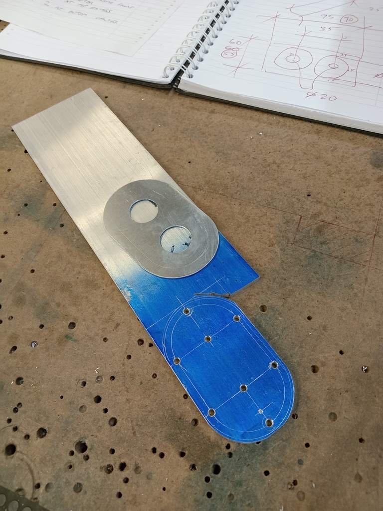
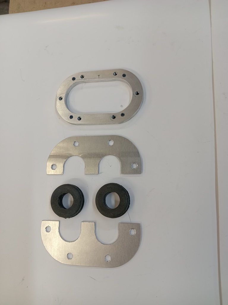
You may wonder at the rather fussy panel details around the fuel fillers. I originally planned to provide access to the fillers though a hatch in the covers, but then on refection it seemed that would be a hassle. You already have to open the doors to access the fillers. So then I thought to fabricate angled spigot flanges to bring the filler caps up to the top face of the top panels. I made up a template to establish the angle cuts. I bought a length of 101 mm (4") diameter pipe and had the flanges lazer cut. Fitting up the parts was complicated by the fact that I angled the fuel tank mountings in the chassis by 1.5 degrees longitudinally to ensure all the fuel can be picked up with the connection points at the rear of the tanks, and as I wanted the filler caps to sit parallel to the panels.
I then fitted up closing panels around the spigots with a 5 mm (1/4") gap to suit a rubber molding I found that has a continuous clip in it that grips the panel edge, and also has a bulb at the end to ensure a snug fit. I have put drain holes though the skin at the bottom of the side pods so that any leak inside the pods will become evident.


I decided the split the main side top panel in two, with the option to remove either end independently depending on which end of the main side pod you wish to access.
On the passenger side the rear lower section of the side pod alongside the engine will contain most of the fuel system parts.
On the driver side it is reserved for a future dry sump oil tank.
On the passenger side the forward section of the side pod is empty.
On the driver side an electric water pump (one of two on the car) will be fitted. This will be accessed though the panel on the front of the side pod, the panel has 2 holes for the water pipes to exit towards the front mounted radiator.
The foremost top panel, on the right is this picture, will be riveted to the chassis as it will have the body scuttle and door hinge support mounted on top of it. I have not riveted it yet as I still have to finalize the wiring harness securing / routing and this will be easier with it out of the way. The recess at the bottom is to accommodate the door edge around the hinge pin as it opens.
You may wonder at the rather fussy panel details around the fuel fillers. I originally planned to provide access to the fillers though a hatch in the covers, but then on refection it seemed that would be a hassle. You already have to open the doors to access the fillers. So then I thought to fabricate angled spigot flanges to bring the filler caps up to the top face of the top panels. I made up a template to establish the angle cuts. I bought a length of 101 mm (4") diameter pipe and had the flanges lazer cut. Fitting up the parts was complicated by the fact that I angled the fuel tank mountings in the chassis by 1.5 degrees longitudinally to ensure all the fuel can be picked up with the connection points at the rear of the tanks, and as I wanted the filler caps to sit parallel to the panels.
I then fitted up closing panels around the spigots with a 5 mm (1/4") gap to suit a rubber molding I found that has a continuous clip in it that grips the panel edge, and also has a bulb at the end to ensure a snug fit. I have put drain holes though the skin at the bottom of the side pods so that any leak inside the pods will become evident.
In order to make the panel over the front of the cockpit and the pedal box cover I had to temporally position the scuttle back on the chassis. I haven't yet put fasteners through the returns against the scuttle and I have made provision to accommodate a few mm of longitudinal adjustment of the scuttle when the body is finally fitted.
With that done I stored the scuttle in the rafters in order to clear the decks for the fun bit - final assembly!
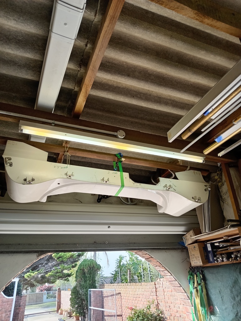
With that done I stored the scuttle in the rafters in order to clear the decks for the fun bit - final assembly!
Looks like you are building an aircraft! The craftsmanship is impressive.
Thanks for the kind responses Guys
In preparation for fitting all the parts that have been taking up space on shelves for so long I took a bit of time to do some housekeeping in the garage and did a stock take of fasteners etc. This are the M6 fastener trays for example.
For fasteners M6 and smaller I generally use only stainless fasteners.
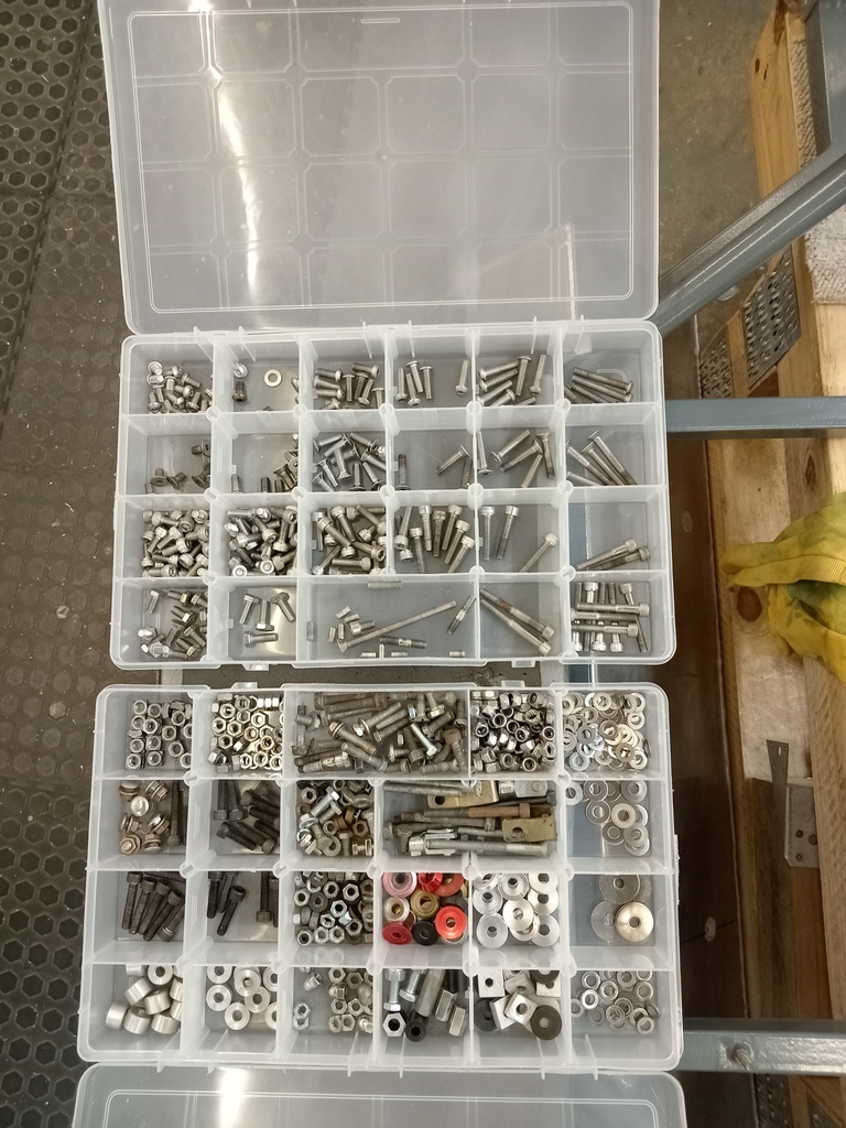
For fasteners M6 and smaller I generally use only stainless fasteners.
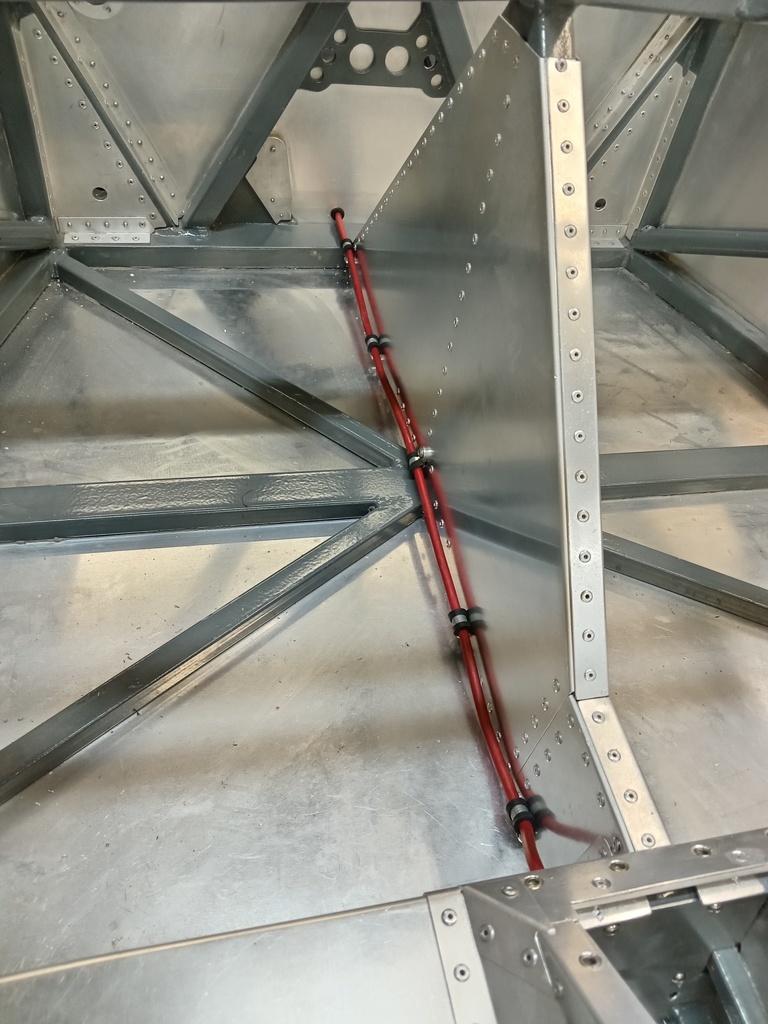
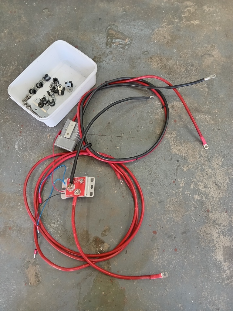
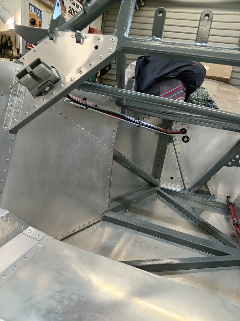
I thought to start from the bottom center of the car and work outwards and upwards. With that logic the first part to fit would be the main power cable running from the starter motor at the rear down the center of the car to the battery in the front.
To position it I first had to fit the battery. I'm using a 30 amp battery usually intended for power sports items such as jet skis and large motorcycles. It weighs 9.4 kg (20.7 pounds). I made a tray to hold the battery. The vertical rods that tie it down are threaded bar. I put electrical heat shrink tubing over them to tidy up the look. These parts add up to 1.3 kg (2.9 pounds).
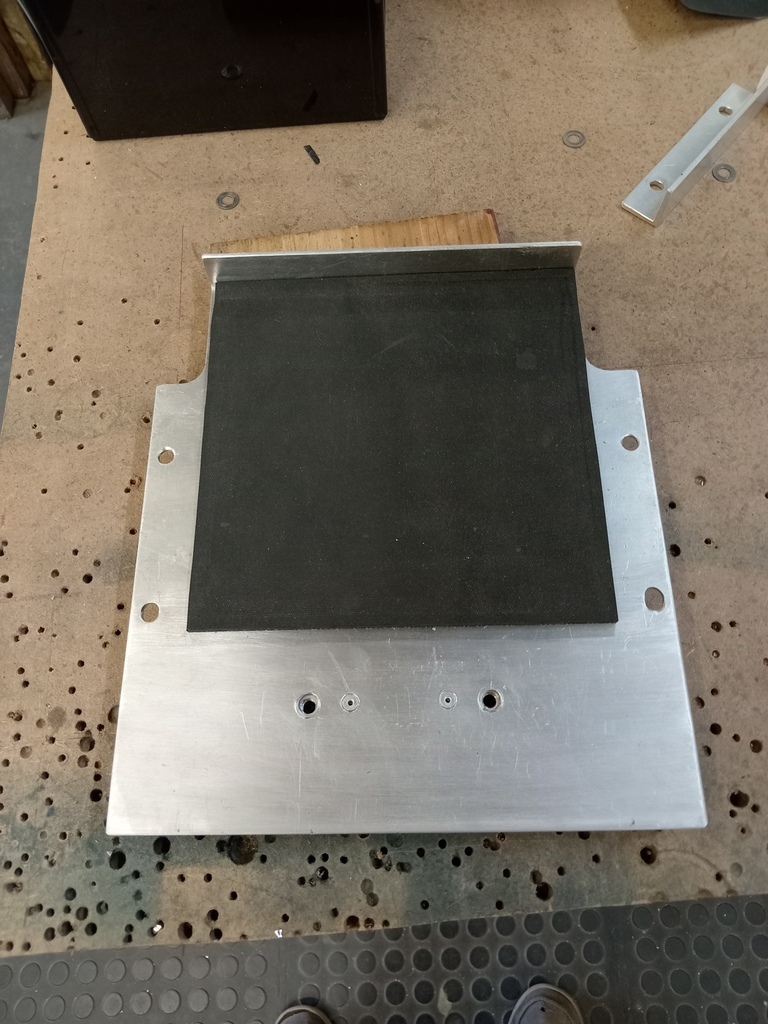
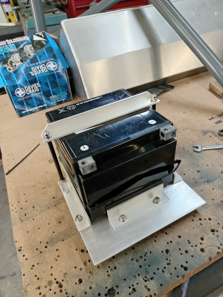
The tray bolts to some brackets welded into the chassis.
I am using a Cartek remote battery isolator. This is mounted near the battery to minimize the length of the large cables and is triggered by a button on the dashboard and another mounted to the body exterior.
As the nose of the car is not hinged and has to be removed by 2 people I wanted to be able to connect an auxiliary battery or charger without removing the nose. So I fitted an Anderson connecter just under the dashboard that is connected directly to the battery. These items and the wiring added up to 1.4 kg (3 pounds).
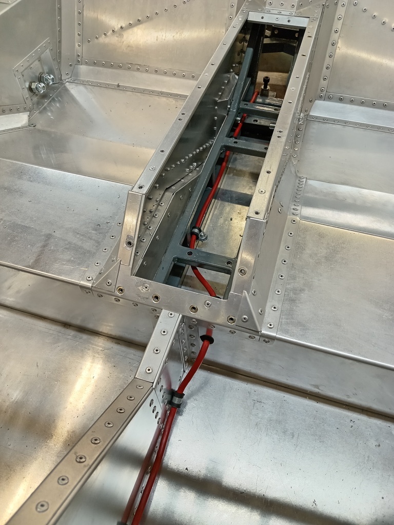
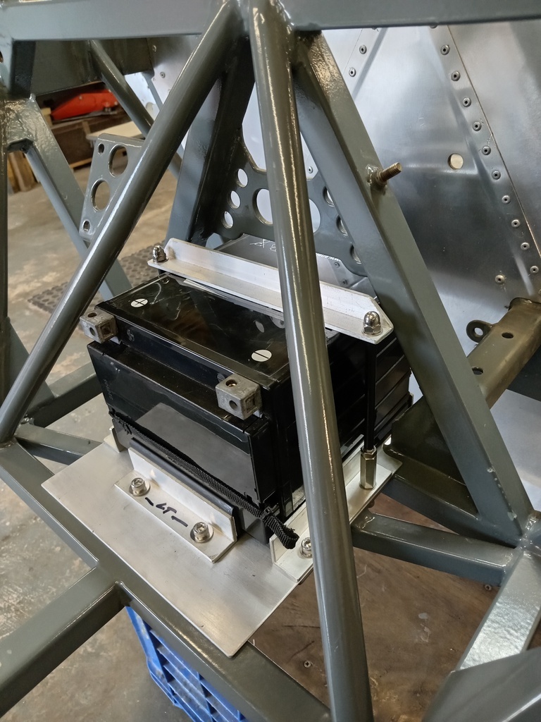
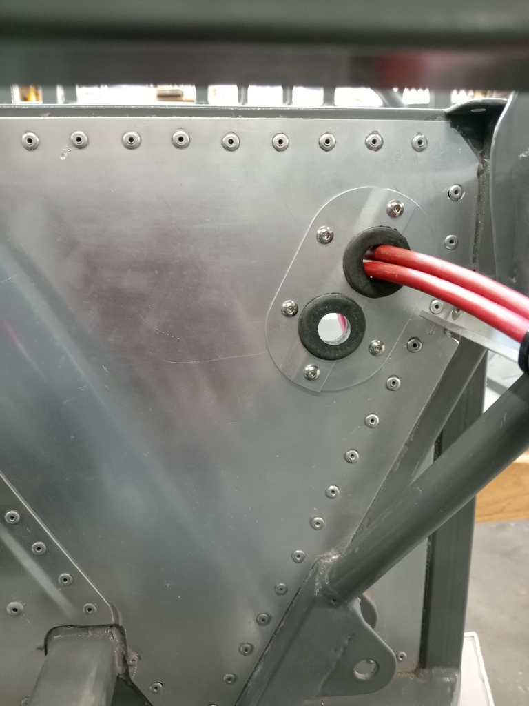
I made a removable plate with grommets to allow the cables and forward wiring loom to pass through the front bulkhead.
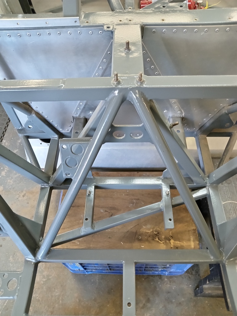
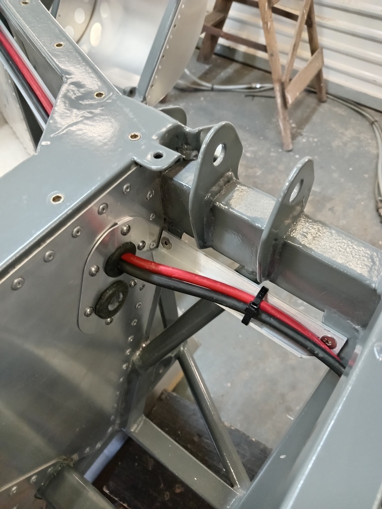
I had welded brackets into the chassis to bolt aluminum angles to to aid in the cable management.
Here you see the position of the battery isolater and the various cables that will connect to the battery. These are not yet finally cable tied.
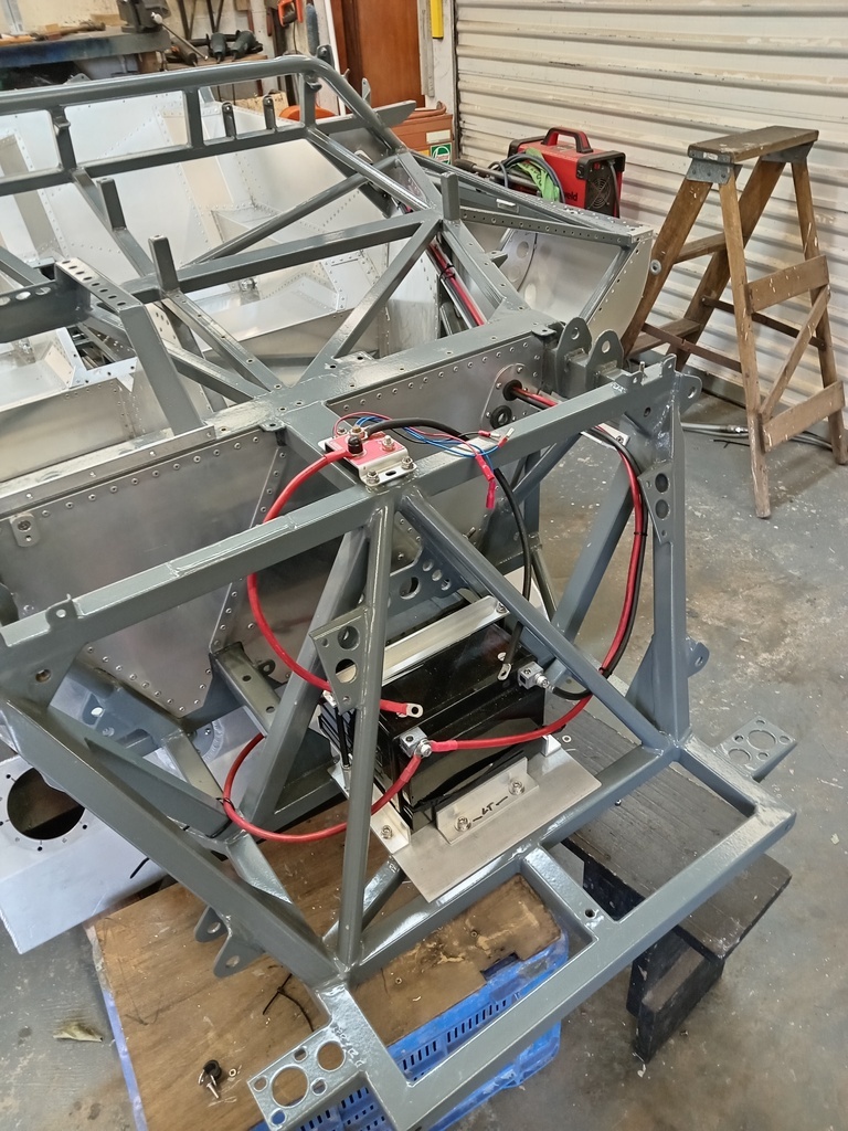
To position it I first had to fit the battery. I'm using a 30 amp battery usually intended for power sports items such as jet skis and large motorcycles. It weighs 9.4 kg (20.7 pounds). I made a tray to hold the battery. The vertical rods that tie it down are threaded bar. I put electrical heat shrink tubing over them to tidy up the look. These parts add up to 1.3 kg (2.9 pounds).
The tray bolts to some brackets welded into the chassis.
I am using a Cartek remote battery isolator. This is mounted near the battery to minimize the length of the large cables and is triggered by a button on the dashboard and another mounted to the body exterior.
As the nose of the car is not hinged and has to be removed by 2 people I wanted to be able to connect an auxiliary battery or charger without removing the nose. So I fitted an Anderson connecter just under the dashboard that is connected directly to the battery. These items and the wiring added up to 1.4 kg (3 pounds).
I made a removable plate with grommets to allow the cables and forward wiring loom to pass through the front bulkhead.
I had welded brackets into the chassis to bolt aluminum angles to to aid in the cable management.
Here you see the position of the battery isolater and the various cables that will connect to the battery. These are not yet finally cable tied.
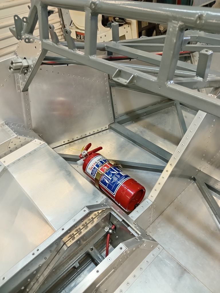
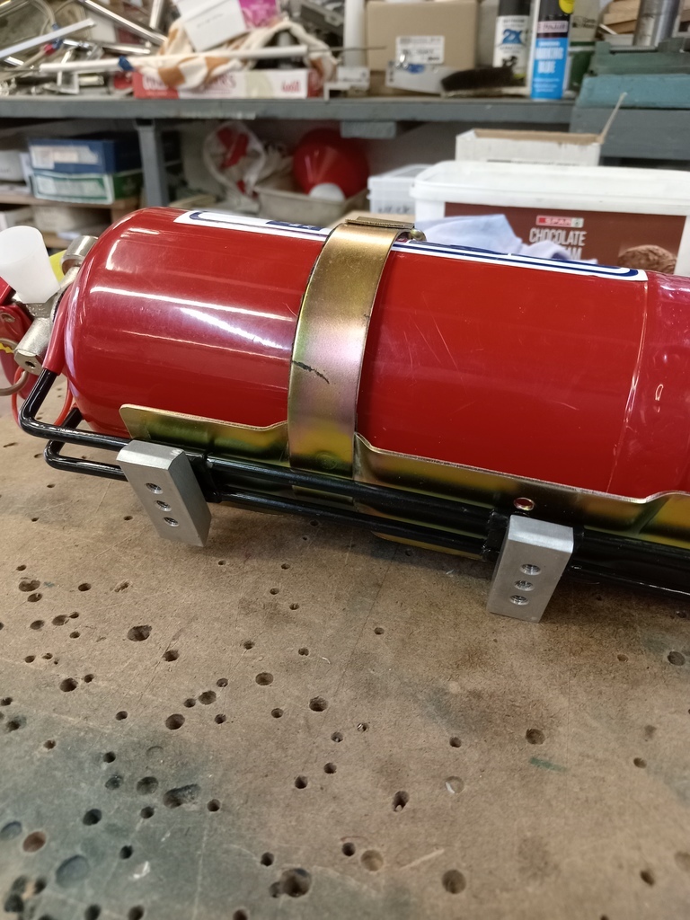
I fitted a fire extinguisher to the floor just in front of the passenger seat. I made some aluminum blocks with tapped holes so that that it could be mounted with the fasteners coming up though the floor. The extinguisher was supplied with a sprung mounting bracket. I bought another bracket that used a positive locking clamp and cut it down so that it could be used in conjunction with the spring clamp. This assembly weighs 2.1 kg (4.6 pounds).
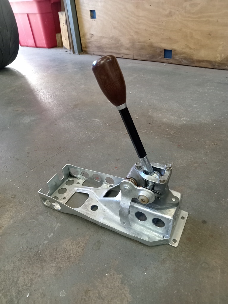
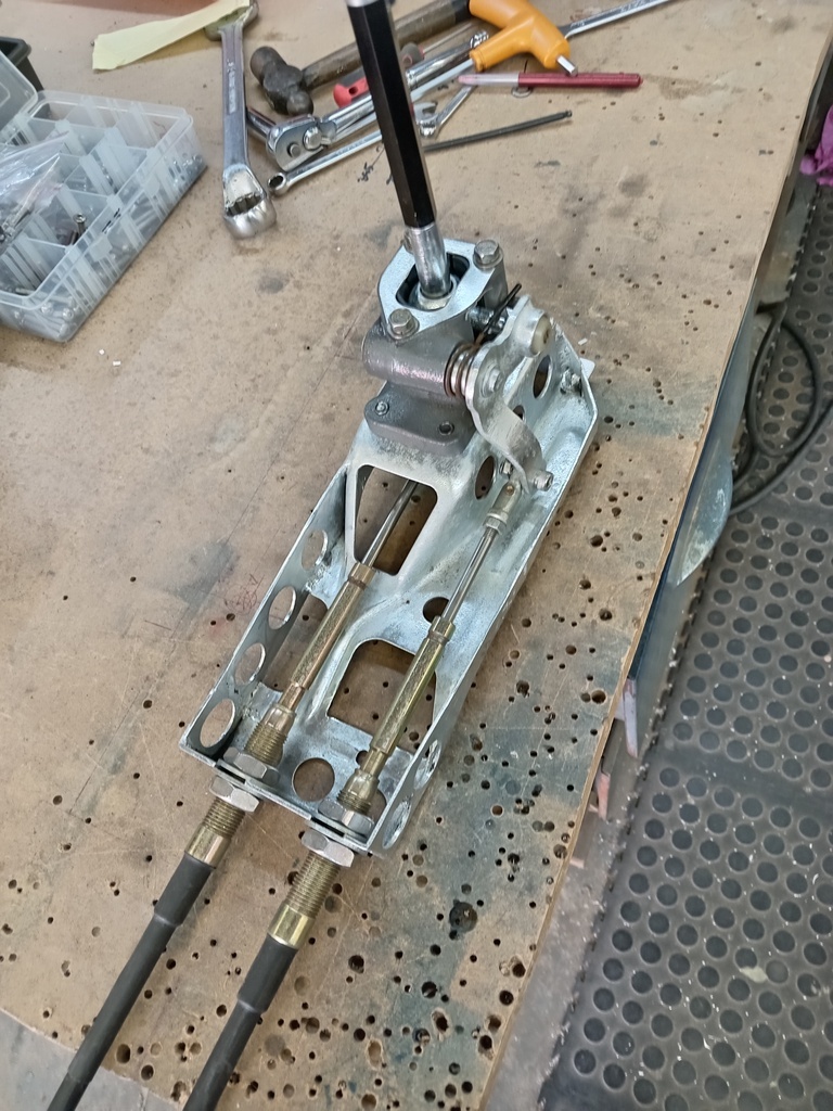
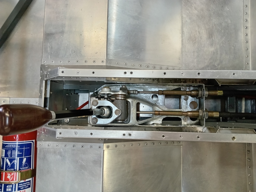
The cable gear change lever assembly comes from an 80s Toyota Corolla, as used by many replicas. Although in my case somewhat modified.
I cut down the original gear lever and welded on a bolt. This threads into an extruded aluminum hollow hex bar to form the gear lever. The hex bar is available as kart steering tie rods. The cable attachments are changed to M6 connections rather than the original "C" clips on pins. The knob was made in Australia some years ago as part of a batch by an esteemed member of this parish. The ferrule between the shaft and the knob was turned by a friend.
Instead of welding brackets to the chassis for the cable attachments I modified the Toyota mounting bracket so that the assembly could be made up on the bench and the cables then just slid into the chassis and the mounting bolted down into weld nuts.
After modification I had the various parts plated.
The assembly weighs 1.7 kg (3.8 pounds). I had bespoke cables made, the 2 of them weigh 1.6 kg (3.5 pounds) with the M6 rod end attachments.
Not a big update, Id neglected to document the installation of the handbrake. The lever is a VW part from a MK 1 Golf, slightly modified.

I had to make up some spacers to lift the handbrake 16 mm from the brackets I had welded into the chassis

I made aluminum brackets to connect to and mount the cables, which are new MK 2 Golf GTi parts, to match the rear calipers I'm using. The lever and the 2 cables weigh 1.41 kg (3.1 pounds) in total.

The Golf Mk 1 continued in production in South Africa until 2009, (in Citi Golf guise) and are still very common on the street and as grass roots competition cars so parts are still plentiful.
It got quite busy in the center tunnel. All bolts here go into weld nuts or rivetnuts so can be tightened with access only from above.

I had to make up some spacers to lift the handbrake 16 mm from the brackets I had welded into the chassis
I made aluminum brackets to connect to and mount the cables, which are new MK 2 Golf GTi parts, to match the rear calipers I'm using. The lever and the 2 cables weigh 1.41 kg (3.1 pounds) in total.
The Golf Mk 1 continued in production in South Africa until 2009, (in Citi Golf guise) and are still very common on the street and as grass roots competition cars so parts are still plentiful.
It got quite busy in the center tunnel. All bolts here go into weld nuts or rivetnuts so can be tightened with access only from above.