Chuck and Ryan's RCR Build

Chuck

Supporter
Fuel Tanks

Our RCR GT-40 as originally designed uses the space in the side sponsons as fuel tanks. There is no liner or separate tank. This works fine, and maximized fuel capacity, but when we learned that separate fuel tanks that would fit inside the sponsons were available we decided to upgrade. This was not a simple project, primarily because of the cutting needed to remove the fill spout and the baffles. On a new installation the process would be much easier.

The fuel tanks come with a 2” filler and a vent bung on the front and a standard sender plate fitting and pick up tube on the rear. These are stout, solid fuel tanks.
 

Attachments

  • FuelTank2.JPG
    FuelTank2.JPG
    294.5 KB · Views: 527
  • FuelTank3.JPG
    FuelTank3.JPG
    311.8 KB · Views: 506
  • FuelTank4.JPG
    FuelTank4.JPG
    287.8 KB · Views: 437
Hi Chuck,
Regarding the step in the tank, I can see more fuel can be held but is it advisable for the inlets to potentially be below the fuel levels ?
Neat welding job though, I do like to see quality.
I'm looking at designing some fuel tanks myself at the moment.
 

Chuck

Supporter
Hi Chuck,
Regarding the step in the tank, I can see more fuel can be held but is it advisable for the inlets to potentially be below the fuel levels ?
Neat welding job though, I do like to see quality.
I'm looking at designing some fuel tanks myself at the moment.

Good question, but I don't think it will be an issue. The top of the inlet tube is essentially even with the top of the tank. Probably no different than filling the tank to near the top of the filler tube. Hope to find out soon . . .

The welding by RCR is top notch. The joints are actually folded over and then welded to provide a stronger joint than a simple butt / corner joint would yield. The weld bead on the ends is nearly a half inch wide, nearly perfect "stack of dimes" weld. Impressive.
 

Jim Rosenthal

Supporter
Chuck, these look a lot like the tanks John Shriver made up for my car. Only real difference is that we isolated the aluminum tanks from the insides of the steel sponsons to avoid any electrolysis issues. Yours are bigger than mine- there must be more room in the sponson area of an RCR than a David Brown chassis. Very nicely done, though- admirable fabrication work.
 

Chuck

Supporter
Chuck, these look a lot like the tanks John Shriver made up for my car. Only real difference is that we isolated the aluminum tanks from the insides of the steel sponsons to avoid any electrolysis issues. Yours are bigger than mine- there must be more room in the sponson area of an RCR than a David Brown chassis. Very nicely done, though- admirable fabrication work.

Ours will also be isolated from the chassis. Not necessarily by design, but because the tank will be supported on rubber blocks. Since it is aluminum on aluminum electrolysis should not be an issues even if it was in contact with the chassis. With a steel chassis, good idea.
 

Randy V

Moderator-Admin
Staff member
Admin
Lifetime Supporter
Chuck - have you already started work on the original sponsons? Will be interested in seeing how you address the baffles inside. That was a showstopper for me when considering the fuel cells that Fran also sells.
 
The tanks that Chuck has are available from us in bladder or in aluminum (shown in Chucks pictures),

The bladders are FIA FT3 world wide race compatible.
 

Chuck

Supporter
Fuel Tanks, Preparation, Part I

The front suspension has to be dissembled to provide access. The brake caliper and rotor were removed. The upper control arm was disconnected from the chassis and the suspension assembly simply folded down to ground level. This avoids having to remove the ball joints. This actually provided a convenient place to rest your back, because one will be spending a lot of time lying on the floor to make the cuts.

The fuel tanks must be drained. We used the fuel pumps to extract as much of the fuel as possible then drilled a half inch drain hole at the aft end of the sponson. This is probably a good idea regardless, since one would want to make sure there was a way residual moisture could escape from the area outside the new tanks within the sponson.

A pattern was made which was slightly larger than the front end of the fuel tanks. Holes were drilled in the front of the sponson to mark the corners. The air saw was used to cut the opening. One is actually cutting through two layers of aluminum: the outer layer is ¼ inch thick and the inner is set in about a quarter inch and seals the fuel tank. (On a new build there would be no inner layer.)

There are two baffles inside the sponson and both need to be cut away. The forward baffle can be reached from the front. Ours were welded, alternating on both sides, along the top and inside edges. These baffles are solidly mounted, which really adds to the joy of removing them. The air saw was used to cut away the baffle to within a quarter inch or so. A grinder with a flapper wheel smoothed the edges.

In order to access the rear baffle, an access panel must be cut in the top of the sponson. The original GT had a similar arrangement. We used a 4” x 6” cover plate from ATL Fuel Cells, part number TF-109 which is available from Summit. The plate was located 7 inches from the forward end and 3 ¼ inches from the inside edge. This opening was cut with a sabre saw. The screw holes were drilled and tapped for a ¼” x 20 bolts. (We did not use the bolts supplied with the plates because they are fine rather than coarse threads. When tapping aluminum, coarse threads are preferred.)

Once the baffles are removed the tank can be set in place, pushed all the way to the rear, and the precise location for the filler tubes determined. We cut the first filler tube with the angled die grinder, but that proved a tedious and time consuming project. The second time we cut an opening around the filler pipes approximately 3 by 4 inches in the location necessary to install the new tanks. Cutting this opening is best accessed from the inside of the tank. If one were to remove the dashboard, even better access could be had.

A rectangular opening 5 ½ x 3 inches was cut at the rear to provide access to the sending unit and the pick-up tube. On our car this will be concealed by the “wings”. A cover plate could be cut to fit if one does not have the “wings.”

I suspect that most of the foregoing preparation would not be needed on a new installation. Has anyone else done a retrofit like this?
 

Attachments

  • FuelTankSponsonD.JPG
    FuelTankSponsonD.JPG
    357.4 KB · Views: 536
  • FuelTankMeasure.JPG
    FuelTankMeasure.JPG
    213.7 KB · Views: 521
  • FuelTankSponsonC.JPG
    FuelTankSponsonC.JPG
    325.1 KB · Views: 571
  • FuelTankSponsonE.JPG
    FuelTankSponsonE.JPG
    386.8 KB · Views: 530
A few of the earlier UK guys had to do this mod due to their time of registration and IVA/SVA rule changes.

You are correct in that all the RCR monocoque chassis now have individual tanks as standard...and have had for a couple of years....
 

Chuck

Supporter
Fuel Tank Preparation, Part II

Before the tanks were installed, a couple of items were addressed.

At Fran’s suggestion, anti-slosh foam was added. Six blocks, each 14” x 3” x 6”, were ordered from Summit (Part # SUM-290190). These block were then cut into four section, about 6” x 3” x 3 ½”. They were then squeezed into the sender opening and pushed sideways forward until all were in place. A notch was cut out of the last section to clear the fuel sender induction tube.

The amount of foam used does not fill up the tank. I would estimate about 70% of the space is filled. The foam should expand about 25% when filled with fuel. In any event, any amount of foam will reduce the fuel slosh, so solid coverage is not required.

There are reports of fuel tank foam deteriorating over time and then clogging the fuel filters. Internet blogs suggest its life is typically around five years. One advantage of these fuel tanks is that they can be removed from the car without too much difficulty, stood on end, and then the foam pulled out the same way it was pushed in. If and when it needs replacement, it can be done.

The sending units were installed. 1 ¼” 10-24 stainless screws were used, after retapping the threaded openings on the tank. The sending units were cut to 5 ½” by Speedhut which leaves 3/4 inch of clearance. In other words, the gauge will read empty when there is still a good bit of fuel in the bottom of the tank: probably a good idea.
 

Attachments

  • FuelTankFoam.JPG
    FuelTankFoam.JPG
    388 KB · Views: 432
  • FuelTankFoam2.JPG
    FuelTankFoam2.JPG
    237.3 KB · Views: 375
  • FuelTankSender1.JPG
    FuelTankSender1.JPG
    279.7 KB · Views: 463

Chuck

Supporter
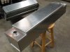
Fuel Tank: Installation

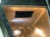
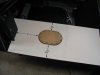
The fuel tanks have to be supported inside the sponson. Note that the sides and top of the fuel tank are parallel to the inside of the sponson but the bottom is not. I suspect this was by design since it creates a deeper valley along the inside edge of the tank where the fuel pick-up is located; a good idea. But this also means that the supports on the bottom of the tank must be different heights on the inside and outside edges.

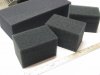
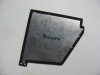
We opted to use rubber strips, ½” and ¼” thick which come in two inch wide strips. Two inch square sections were cut from these strips. The material selected came from McMaster Carr and is neoprene rubber, 40A durometer. This is a bit harder than a pencil eraser, providing some cushioning effect, but very little compression. It is also oil resistant. Part numbers: 8546K437 and 8456K435. We ordered the material that had adhesive on one side. The adhesive does not work well and would suggest ordering the same item without the adhesive.

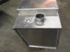
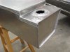
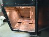
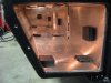
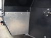
Six blocks were used to support the bottom of the tank: three each quarter inch thick on the inside and three each half inch thick on the outside. Two blocks on the inside vertical were placed midway top to bottom, one fore and one aft. These are ¾” thick made by gluing a ¼” and ½” together. Remember to place a half inch block at the rear end to keep the tank from touching the aft bulkhead. Finally blocks were placed on the outside to tighten up the tank, left to right, as the tank was slid into place. The picture shows the blocks in place. (We removed the center vertical block after the picture was taken – not necessary).

3M black weather strip adhesive was used to secure the blocks. It works well. After applying a coat to both surfaces, it was left to dry for about ten minutes then pressed into place.

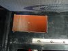
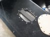
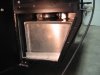
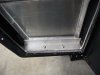
The tank is inserted, being careful not to knock the blocks loose. Wiping Griot’s car wash soap on the blocks also helps slide the tank in. When the tank is nearly all the way back, another block is glued on the outer most surface of the sponson, permitted to set up, then the tank pushed in the last couple of inches, lifting as it is guided in. Because of the angles, this block will be tighter as one pushes it lower, so it was not glued in advance. A block was added near the front on the outer most surface of the sponson after the tank was pushed all the way in, again pushing it lower to make it tighter. (That block is visible in the photo)

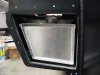
Finally, a length of one inch insulating foam was placed under the access plates which compresses on the tank from the top. Once the plates are screwed down the tank is secure.
 

Attachments

  • FuelTankSupportBlocks.JPG
    FuelTankSupportBlocks.JPG
    352.7 KB · Views: 505
  • FuelTankInstalled1.JPG
    FuelTankInstalled1.JPG
    332.8 KB · Views: 500
  • FuelTankCover.JPG
    FuelTankCover.JPG
    360 KB · Views: 439

Randy V

Moderator-Admin
Staff member
Admin
Lifetime Supporter
Wow.... What a great turn out for such a tough job... Kudos to you guys!!! :thumbsup:
 

Chuck

Supporter
Completing the Fuel Tank Install

The filler hose is clamped to the filler tube by accessing the clamp from the front opening. It cannot be accessed once the front is covered. The fuel filler hose is sold by Summit, part DAC-80306. A three foot length was ordered, which is plenty to connect the aluminum angle sections from RCR.

Fittings for the vent and filler tubes were placed after the tank was installed: 5/16” x ¼” hose barb. A loop was added to the vent hose to reduce surging of fuel when refueling.

To prevent the tank from sliding forward a one inch aluminum angle, 1/8” thick and cut 7 ½ inches long was used. Holes were drilled and taped and quarter inch diameter x 20 stainless screws used so it could be accessed without removing the fiberglass rocker panels. We did not want to use the cover plate to keep the tank from sliding forward, hence this arrangement.

A cover plate for the front of each sponson was fabricated. A section of .10 thick, 6061 aluminum was cut larger than the opening after a pattern was made. Quarter inch x 20 screw holes were tapped at several locations. Stainless button head screws were used since we don’t want any rust. Foam tape was used to help seal between chassis and the plate. Later we may paint the cover plates to match the powder coated chassis, but I doubt this panel will be very noticeable once the GT is back together.
 

Attachments

  • FuelTankFiller.JPG
    FuelTankFiller.JPG
    268.1 KB · Views: 412
  • FuelTankBracket.JPG
    FuelTankBracket.JPG
    304 KB · Views: 440
  • FuelTankCoverTape.JPG
    FuelTankCoverTape.JPG
    234.7 KB · Views: 420
  • FuelTankCover1.JPG
    FuelTankCover1.JPG
    329.7 KB · Views: 386

Brian Kissel

Staff member
Admin
Lifetime Supporter
AS always, nice work Chuck. What is the total capacity of the two tanks ?? And also, do you know what the capacity is if you use the bladders.

Regards Brian
 

Chuck

Supporter
AS always, nice work Chuck. What is the total capacity of the two tanks ?? And also, do you know what the capacity is if you use the bladders.

Regards Brian

Good questions. Don't know the answer. When I fill the tanks (soon I hope) for the first time I will post the gallons of fuel it holds.
 
Back
Top