An alternative to a Forstner bit is an aircraft counterbore. It is similar but the pilot is round and sized to the hole diameter.Headrest and Tailfin, Part III
Countersunk screws in fiberglass will inevitably cause cracks to develop unless measures are taken to distribute the force of the screw’s head. We used countersunk Timmerman washers to address this concern.
First, a half-inch Forstner bit was used to remove the gel coat and drill just deep enough so that the Timmerman washers set fractionally below the surface.
View attachment 149883
Second, a Dremel tool with a tapered grinder was used to open the hole so that the washer could be set in place.
View attachment 149884
Third, a layer of fiberglass about an inch and a half wide was laid on the bottom side to reinforce the holes.
View attachment 149885
Next, the area around the openings was sanded to blend the fiberglass/flox rather than leaving a sharp line. The washers were epoxied in place. Once dry, the surface was sanded smooth, and the tapered openings on the washers were cleared of material.
View attachment 149886
View attachment 149887
Once painted, the washers will be invisible, and only the heads of the screws will be seen, which will likely be touched with a dab of body paint, making them look like flush rivets to the casual observer. Stainless 1-inch #6-30 button-head screws and Nyloc nuts with large washers on the bottom side are used.
View attachment 149888
This was a lot of work to make the headrest and tail fin removable, but it will simplify construction and painting moving forward.

You are using an out of date browser. It may not display this or other websites correctly.
You should upgrade or use an alternative browser.
You should upgrade or use an alternative browser.
Chuck's Jaguar D Type Build
- Thread starter CESLAW
- Start date
Good point, Neil. I did indeed try an aircraft bore (which I have used for the same function on aircraft), but because of the fiberglass RCR used, it left an irregular, rough surface, so I went with the Forstner bit and the Dremel.An alternative to a Forstner bit is an aircraft counterbore. It is similar but the pilot is round and sized to the hole diameter.
Rear-end alignment.
The quarter-inch discrepancy between the subframe and the brake calipers, noted in an earlier post, required attention. This discrepancy was also apparent between the wheel openings and the tires. We needed to move the rear axle one-quarter inch toward the driver’s side.
This project confirmed the benefit of a removable rear clip. The tires and the fuel tank were removed, providing good access to the suspension. Moving the axle was accomplished by adjusting the forward connections of the lateral support, lengthening on the left and shortening on the right.

After adjusting, the measurement between a point on the inside of the wheel rim and the subframe was within an eighth of an inch left to right (approximately 2 millimeters).

The rear clip was replaced. After confirming the tires were inflated to the same pressure, measurements were taken from the center point of the top of the outer wheel well opening to the edge of the tire rim and from that same point to the floor. These dimensions were within 1/8 of an inch side to side. Given the significant variations in the fiberglass body observed during front clip setup, we are both surprised and pleased.
More chassis alignment will likely be needed later, but for now, the suspension is well within an acceptable range to proceed with the fiberglass bodywork.
The quarter-inch discrepancy between the subframe and the brake calipers, noted in an earlier post, required attention. This discrepancy was also apparent between the wheel openings and the tires. We needed to move the rear axle one-quarter inch toward the driver’s side.
This project confirmed the benefit of a removable rear clip. The tires and the fuel tank were removed, providing good access to the suspension. Moving the axle was accomplished by adjusting the forward connections of the lateral support, lengthening on the left and shortening on the right.
After adjusting, the measurement between a point on the inside of the wheel rim and the subframe was within an eighth of an inch left to right (approximately 2 millimeters).
The rear clip was replaced. After confirming the tires were inflated to the same pressure, measurements were taken from the center point of the top of the outer wheel well opening to the edge of the tire rim and from that same point to the floor. These dimensions were within 1/8 of an inch side to side. Given the significant variations in the fiberglass body observed during front clip setup, we are both surprised and pleased.
More chassis alignment will likely be needed later, but for now, the suspension is well within an acceptable range to proceed with the fiberglass bodywork.
Headrest and Tailfin, Part IV
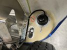
The fuel filler lid was held in place with a pair of sturdy stainless-steel hinges found at an ACE Hardware store. They resemble those used on the original reasonably well. Temporarily set in place, the poor alignment of the lid was apparent. A significant amount of time was spent refining the fit.

The hinges were slightly countersunk to shrink the gap on that surface. Material was ground from the lid to ensure the screws had clearance. When opened, the aft end of the lid bumped the forward end of the fin, requiring that material be removed from the fin. This will require adding fiberglass material to the top portion of the fin opening to ensure an even gap when we get deeper into the bodywork.

There are more irregularities around the mating surfaces, which will be corrected later.

Remaining to be done is the design and fabrication of the locking button.
The fuel filler lid was held in place with a pair of sturdy stainless-steel hinges found at an ACE Hardware store. They resemble those used on the original reasonably well. Temporarily set in place, the poor alignment of the lid was apparent. A significant amount of time was spent refining the fit.
The hinges were slightly countersunk to shrink the gap on that surface. Material was ground from the lid to ensure the screws had clearance. When opened, the aft end of the lid bumped the forward end of the fin, requiring that material be removed from the fin. This will require adding fiberglass material to the top portion of the fin opening to ensure an even gap when we get deeper into the bodywork.
There are more irregularities around the mating surfaces, which will be corrected later.
Remaining to be done is the design and fabrication of the locking button.
Wiring, Front End
The original D Types did not have orange front marker/turn signal lights, but they were often added, presumably to make them street-legal. We do not like the look of the orange marker lights mounted on the front fenders. Some original D Type owners put the orange marker lights inside the light housing, which was an improvement, but still looked awkward.
The headlights from RCR have the usual high/low beams, with a small light using a VCH 1112 bulb near the base of the reflector. We decided to wire this small light to the parking light circuit, avoiding the need for the orange marker light. We experimented replacing it with a much brighter LED, but did not like the look, so the incandescent bulb was retained.
Below the headlight is a separate small light that is being wired as the turn indicator, obtained from Moss Motors. Part number C4517. Technically, it should be the smaller fender lamp, part number C14929, but the larger lamp holds a brighter 1156 light bulb. With the front lighting sorted out in this manner, the D should meet registration requirements without that obtrusive orange marker light.
A bracket to support the turn indicator was designed and fabricated. Once wired, it produced a nice, bright beam. This light will remain with an incandescent bulb because it will be visible when looking into the light well.

As on the original, a fabric-covered wire was connected to the parking light, now the turn signal lamp. In this picture, the turn indicator and internal marker light are illuminated.

A wire harness with Deutsch connectors was installed on both sides so the bonnet could be “unplugged” when removed. The wires were marked with Dyno heat shrink labels. The wire harness was laid out, wrapped, and secured with aluminum clamps to look like an original example. The original style junction box, mounted behind the radiator so long ago, simplified the wiring process.

Next is wiring the rear end.
The original D Types did not have orange front marker/turn signal lights, but they were often added, presumably to make them street-legal. We do not like the look of the orange marker lights mounted on the front fenders. Some original D Type owners put the orange marker lights inside the light housing, which was an improvement, but still looked awkward.
The headlights from RCR have the usual high/low beams, with a small light using a VCH 1112 bulb near the base of the reflector. We decided to wire this small light to the parking light circuit, avoiding the need for the orange marker light. We experimented replacing it with a much brighter LED, but did not like the look, so the incandescent bulb was retained.
Below the headlight is a separate small light that is being wired as the turn indicator, obtained from Moss Motors. Part number C4517. Technically, it should be the smaller fender lamp, part number C14929, but the larger lamp holds a brighter 1156 light bulb. With the front lighting sorted out in this manner, the D should meet registration requirements without that obtrusive orange marker light.
A bracket to support the turn indicator was designed and fabricated. Once wired, it produced a nice, bright beam. This light will remain with an incandescent bulb because it will be visible when looking into the light well.
As on the original, a fabric-covered wire was connected to the parking light, now the turn signal lamp. In this picture, the turn indicator and internal marker light are illuminated.
A wire harness with Deutsch connectors was installed on both sides so the bonnet could be “unplugged” when removed. The wires were marked with Dyno heat shrink labels. The wire harness was laid out, wrapped, and secured with aluminum clamps to look like an original example. The original style junction box, mounted behind the radiator so long ago, simplified the wiring process.
Next is wiring the rear end.
You have a sharp eye and are absolutely correct. Although I only need two grommets, I have a package of 50 because that is the smallest quantity McMaster-Carr sells them in. I decided to wait to install them until after those panels are painted.Hi Chuck, just wondering if you will be using some kind of a rubber grommet on the panel that the small light wire goes though, I understand that fiberglass can be very abrasive.
Nearly everything attached to the body will be removed for sanding, priming, and painting. The plan is to complete the significant fabrication before year-end and start bodywork and paint next year.
Wiring, Rear End, Part 1
The rear end includes the tail/brake light and the separate round marker/turn signal light. Although the red marker lights are not typically seen on the original examples and presumably added to make them road legal, they look decent, and the need for bright blinkers warranted their addition. The kit came with orange marker lights, so proper red ones were ordered from Moss Motors. Part number 143-701.
The light was disassembled and rewired with color-coded wire in accordance with our wiring plan. It has been mentioned in previous posts that British parts must always be carefully inspected to confirm they were done correctly. A couple of the wire connections that came with these lights were loose and could have separated, potentially short-circuiting.

With the parts in hand, the hole locations were determined and the lights installed. Note that the “mould” line on the body is not parallel to the ground, so a level was used to align the light fixtures.

Installing the lights feels like a significant milestone. Next, lay out and complete the wiring.
The rear end includes the tail/brake light and the separate round marker/turn signal light. Although the red marker lights are not typically seen on the original examples and presumably added to make them road legal, they look decent, and the need for bright blinkers warranted their addition. The kit came with orange marker lights, so proper red ones were ordered from Moss Motors. Part number 143-701.
The light was disassembled and rewired with color-coded wire in accordance with our wiring plan. It has been mentioned in previous posts that British parts must always be carefully inspected to confirm they were done correctly. A couple of the wire connections that came with these lights were loose and could have separated, potentially short-circuiting.
With the parts in hand, the hole locations were determined and the lights installed. Note that the “mould” line on the body is not parallel to the ground, so a level was used to align the light fixtures.
Installing the lights feels like a significant milestone. Next, lay out and complete the wiring.
I can confirm Chucks suspicions on the wiring issues. I ordered 4 NOS Lucas lights for my Lola, and two of them had very loose wires.
Regards Brian
Regards Brian
Wiring Rear Lights, Part II. With the rear clip being removable, a means of unplugging the rear lighting harness was needed. We decided to locate a Deutsch six-pin connector under the tail fin near the fuel filler, accessible through an opening that will not be seen when the fuel filler is closed.

The original style junction box mounted between the seats simplified the wiring of the taillight harness.

The wires were color-coded: brown/tail lights; red/left blinker; green/right blinker; yellow/brake. Once laid out and tested, the Painless half-inch wrap was applied and secured with plastic clamps.

Between the six-pin Deutsch connector and the lights, there are no splices or connections. Wires from the parking and tail lights on the right side were routed to the left, the former serving as the “junction box” to join the two sides. Of course, the blinkers required separate dedicated wires. Using the stock incandescent bulbs rather than LEDs, the lights are nice and bright.

Wiring is now finished. Next on the list is the bonnet latches.
The original style junction box mounted between the seats simplified the wiring of the taillight harness.
The wires were color-coded: brown/tail lights; red/left blinker; green/right blinker; yellow/brake. Once laid out and tested, the Painless half-inch wrap was applied and secured with plastic clamps.
Between the six-pin Deutsch connector and the lights, there are no splices or connections. Wires from the parking and tail lights on the right side were routed to the left, the former serving as the “junction box” to join the two sides. Of course, the blinkers required separate dedicated wires. Using the stock incandescent bulbs rather than LEDs, the lights are nice and bright.
Wiring is now finished. Next on the list is the bonnet latches.
Doug:
Have not yet decided on the filler door clip. I ordered a stainless latch from McMaster a couple of weeks ago, but it is on back order. It is not really "original" but may function well. I am also contemplating making a latch like the original from a strip of thin stainless steel. My reservation about that, however, is that it would not be as secure as I would like.
Will keep you posted.
Doug M
Supporter
Thinking about how my remote control gliders and powered airplanes are often built… perhaps magnets can be imbedded in the fiberglass edges of the two mating surfaces? Tiny ones are typically enough to keep a hatch secured on a remote controlled airplane. Since the fuel filler cover is flush and doesn’t take the brunt of wind resistance, all you need is something to keep it from bouncing up and down. Larger magnets could probably do the trick. You might just have to install a tiny tab to get your finger under to open it.

Latches, Part I
Before the latches can be installed, the bonnet and body need to be correctly aligned. Centering pins help.
The centering pins provided by RCR ensured the bonnet would align properly when closed. These same pins are used on the RCR GT-40 kit, but on the Jaguar, we wanted a tighter opening. Accordingly, the pins were placed in the lathe, and the base turned down to 3/32”. Here are the before and after pictures:

These pins come with a nylon socket for attachment to the upper surface, but we opted not to use it because the quarter-inch of fiberglass added to correct the misalignment provided enough thickness to secure the pins.
With the bonnet set precisely in place, a 1/8” guide hole was drilled from the bottom up through the lower sill and bonnet surfaces. The upper opening was then drilled out and tapered to fit the pin with a little ‘wiggle room.’ The bottom hole was drilled out to 5/16”, which provides some adjustability.
The pins were placed two inches from the leading edge of the lower surface.

Next, the latches will be fitted. Here are pictures I snapped of an original, which we are trying to duplicate.


Before the latches can be installed, the bonnet and body need to be correctly aligned. Centering pins help.
The centering pins provided by RCR ensured the bonnet would align properly when closed. These same pins are used on the RCR GT-40 kit, but on the Jaguar, we wanted a tighter opening. Accordingly, the pins were placed in the lathe, and the base turned down to 3/32”. Here are the before and after pictures:
These pins come with a nylon socket for attachment to the upper surface, but we opted not to use it because the quarter-inch of fiberglass added to correct the misalignment provided enough thickness to secure the pins.
With the bonnet set precisely in place, a 1/8” guide hole was drilled from the bottom up through the lower sill and bonnet surfaces. The upper opening was then drilled out and tapered to fit the pin with a little ‘wiggle room.’ The bottom hole was drilled out to 5/16”, which provides some adjustability.
The pins were placed two inches from the leading edge of the lower surface.
Next, the latches will be fitted. Here are pictures I snapped of an original, which we are trying to duplicate.
Doug M
Supporter
Round? Joking. Honestly don’t know. I think any stronger magnet will do. Might even get away with a magnet and flat metal combo vs two magnets.Doug
That is an excellent idea! There are some relatively strong magnets, and that would be a clean, easy solution. If it later turned out it did not work, it would not be difficult to switch to something more conventional. Any magnet recommendations??
Latches, Part II.
Following Doug Maxwell’s lead, original parts were ordered from Ashwater Classics in England for the bonnet and trunk. These parts were crazy expensive by the time import duties and shipping charges were added. The parts include the Bonnet and Boot Handles (02/0013), the Escutcheons (03/0644), and the number plate bracket. https://www.ashwater-classics.co.uk/ The latch mechanism came from Moss Motors. BD16016 and BD16015. (The quality of the grossly overpriced latch mechanism was terrible, requiring that one of the latches be replaced.) The license plate light and trunk lid mechanism also came from Moss Motors.
Time was spent laying out the parts' locations. The inner side was sanded smooth. It is best to start by drilling the 1/2-inch hole through which the latch handle passes. The hole needs to be horizontal. A step drill assured a smooth finish.

Once the central hole is drilled, the two top holes for the mechanism can be match drilled. The lower holes are for screws that are non-functional. Note that the exact location of the latch mechanism depends on the position of the latch pin on the receiver mounted on the lower sill. Dimensions shown are for the left side and should not be considered precise.

The upper tangs on the mechanism were bent slightly to match the body's curve.
Before the mechanism could be installed, the bottom opening on the bonnet had to be cut.

With the cutting done, the latches were temporarily set in place. (The nuts shown are temporary and will be replaced with Nyloc nuts.) Only the top screws hold the mechanism in place. The lower two are “dummies” to match the original's look, which had extensions added to match the body's curve. The fiberglass's thickness provides a solid connection with just the top two screws, so lower extensions, visible in the photo of the original, were not added.

The next project is fabricating the latch receivers.
Following Doug Maxwell’s lead, original parts were ordered from Ashwater Classics in England for the bonnet and trunk. These parts were crazy expensive by the time import duties and shipping charges were added. The parts include the Bonnet and Boot Handles (02/0013), the Escutcheons (03/0644), and the number plate bracket. https://www.ashwater-classics.co.uk/ The latch mechanism came from Moss Motors. BD16016 and BD16015. (The quality of the grossly overpriced latch mechanism was terrible, requiring that one of the latches be replaced.) The license plate light and trunk lid mechanism also came from Moss Motors.
Time was spent laying out the parts' locations. The inner side was sanded smooth. It is best to start by drilling the 1/2-inch hole through which the latch handle passes. The hole needs to be horizontal. A step drill assured a smooth finish.
Once the central hole is drilled, the two top holes for the mechanism can be match drilled. The lower holes are for screws that are non-functional. Note that the exact location of the latch mechanism depends on the position of the latch pin on the receiver mounted on the lower sill. Dimensions shown are for the left side and should not be considered precise.
The upper tangs on the mechanism were bent slightly to match the body's curve.
Before the mechanism could be installed, the bottom opening on the bonnet had to be cut.
With the cutting done, the latches were temporarily set in place. (The nuts shown are temporary and will be replaced with Nyloc nuts.) Only the top screws hold the mechanism in place. The lower two are “dummies” to match the original's look, which had extensions added to match the body's curve. The fiberglass's thickness provides a solid connection with just the top two screws, so lower extensions, visible in the photo of the original, were not added.
The next project is fabricating the latch receivers.
As always, nice work and write up.
Thanks for posting.
Regards Brian
Thanks for posting.
Regards Brian
Latches, Part III. The latch receivers were fabricated. An aluminum U-channel was ordered from McMaster-Carr, 3/4-inch wide and 3/4-inch high. We experimented with both 1/16” and 1/8” thick material and preferred the former in this application.
The U-channel was cut to 2 inches long, shaped to resemble the original, and a 1/8-inch hole was drilled for the latch rod. A one-inch length of stainless-steel rod was placed. For now the rod is secured with push nuts, but later we plan to squeeze the rod to lock it in place.

The receiver was secured to the body with countersunk screws. The latch was located so that a pair of washers could be used under the receiver. By adding or removing washers, there will be some adjustability to ensure a tight fit after the final assembly, once the paint is done. The outer surface of the receiver fits closely against the opening on the bonnet, keeping the sill and bonnet aligned, so the pin must be flush on the outer surface.

The escutcheon presented a problem because the taper is insufficient to lie correctly. Accordingly, a tapered spacer was made using epoxy and Flox. This will eventually be epoxied to the body, a filet added, and painted body color.

Now we can move on to the trunk latch.
The U-channel was cut to 2 inches long, shaped to resemble the original, and a 1/8-inch hole was drilled for the latch rod. A one-inch length of stainless-steel rod was placed. For now the rod is secured with push nuts, but later we plan to squeeze the rod to lock it in place.
The receiver was secured to the body with countersunk screws. The latch was located so that a pair of washers could be used under the receiver. By adding or removing washers, there will be some adjustability to ensure a tight fit after the final assembly, once the paint is done. The outer surface of the receiver fits closely against the opening on the bonnet, keeping the sill and bonnet aligned, so the pin must be flush on the outer surface.
The escutcheon presented a problem because the taper is insufficient to lie correctly. Accordingly, a tapered spacer was made using epoxy and Flox. This will eventually be epoxied to the body, a filet added, and painted body color.
Now we can move on to the trunk latch.
Trunk Latch, Part I. Here are pictures of the originals we used as a guide.


This project started with the receiver. Coming up with a suitable design took a lot of brainstorming, but the solution proved simple. A twelve-inch-long, half-inch U-channel was used. Using the mill, a slot 1.50 inches long was cut.

An opening 1.75 inches was cut in the fiberglass, a quarter inch longer than the opening in the U-channel. The back side of the fiberglass was sanded smooth to ensure a good fit. Note that the channel is mounted flush with the top surface, not the lip. A pair of 1/8” holes was drilled, and clecos were used to hold it temporarily in place. Next, epoxy and flox were used to fill the gap between the lip and the U-channel, ensuring a proper fit between the two surfaces. Note that the opening begins at the center point and extends to the right.

Later, the U-channel will be secured with epoxy and Flox. Rivets will also be added when the weather stripping is applied. Next is the latch mechanism and handle.
This project started with the receiver. Coming up with a suitable design took a lot of brainstorming, but the solution proved simple. A twelve-inch-long, half-inch U-channel was used. Using the mill, a slot 1.50 inches long was cut.
An opening 1.75 inches was cut in the fiberglass, a quarter inch longer than the opening in the U-channel. The back side of the fiberglass was sanded smooth to ensure a good fit. Note that the channel is mounted flush with the top surface, not the lip. A pair of 1/8” holes was drilled, and clecos were used to hold it temporarily in place. Next, epoxy and flox were used to fill the gap between the lip and the U-channel, ensuring a proper fit between the two surfaces. Note that the opening begins at the center point and extends to the right.
Later, the U-channel will be secured with epoxy and Flox. Rivets will also be added when the weather stripping is applied. Next is the latch mechanism and handle.
Similar threads
- Replies
- 1
- Views
- 429
- Replies
- 1
- Views
- 2K