
You are using an out of date browser. It may not display this or other websites correctly.
You should upgrade or use an alternative browser.
You should upgrade or use an alternative browser.
Chuck's Jaguar D Type Build
- Thread starter CESLAW
- Start date
Beautiful piece of machinery-jewelry!
Engine Stand
When the engine was complete, knowing it would be a while before it was placed in the Jag, My son, Ryan, built a custom stand. Using a couple of ten-foot lengths of one-inch square steel, the pieces were cut and TIG welded in our garage on a Saturday afternoon, then sprayed bright red.
.JPG")


A PDF with plans for the stand is attached.
When the engine was complete, knowing it would be a while before it was placed in the Jag, My son, Ryan, built a custom stand. Using a couple of ten-foot lengths of one-inch square steel, the pieces were cut and TIG welded in our garage on a Saturday afternoon, then sprayed bright red.
A PDF with plans for the stand is attached.
Attachments
flatchat(Chris)
Supporter
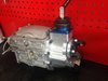
Chris, interesting. So that is a T5 with modified top plate and shifter assembly? Is the location of the shifter same as the original D Type? It looks a bit forward to my uninformed eye.
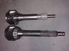
Is the input shaft shortened to match the original Jag tranny length? What bell housing do you use?
Is the input shaft shortened to match the original Jag tranny length? What bell housing do you use?
Bill Kearley
Supporter
Sweet classic stuff. love it.
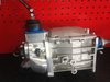
This was the shortening required for the 5Speeds bellhousing mating the Tremec T5 to the 4.2. And it is even 1/4" longer due to a spacer between the bellhousing and trans.
I wanted that to get full engagement of the input shaft spline into the friction plate.
I wanted that to get full engagement of the input shaft spline into the friction plate.
Attachments
flatchat(Chris)
Supporter
A mustang V8 T5 with modified input shaft (usually a 10 spline) and moded output shaft -- cnc billet extension housing with shifter pos ~ 12" from bolt up face
You'd be welcome to contact these guys for more detailed info and costings
https://malwoodauto.com.au/contact-us/
As they are where I earn my pension these days ;-)
We usually add some bolt up lugs to an existing Jag bell also
Speedo drive is for electronic only - pulsater….
You'd be welcome to contact these guys for more detailed info and costings
https://malwoodauto.com.au/contact-us/
As they are where I earn my pension these days ;-)
We usually add some bolt up lugs to an existing Jag bell also
Speedo drive is for electronic only - pulsater….
Last edited:
Chuck nothing wrong with a little variety in life keep posting I find it very interesting and who knows maybe someone else will build the same car in the future so think of it as you being the teacher and we the students
Preliminary Chassis Alignment, Preparation
Before any cutting, gluing or screwing, the chassis was set up in a preliminary fashion. Now the disclaimer: what I am describing here is strictly preliminary and subject to change.
The chassis needs to be setting at proper ride height when adjusting the suspension. An eight foot 2” x 4” was cut into sixteen six-inch lengths. Four sets of four blocks each were glued together to make the height stands. This 6” height will provide the chassis ride height for future chassis adjustments. These height stands will be used repeatedly throughout the construction and later when servicing the car, so they were painted bright red to assure the spouse would not mistake the blocks for fireplace tinder.

While cutting timber, a pair of 2” x 4”s cut to 9 ¼” length will come in handy when setting up the front suspension. We did not paint these red, since once the suspension is in place, they will make great fireplace tinder.

Place two height stands under the rear corners of the monocoque. Place the remaining pair of height stands under the chassis directly below the engine mounts. This is where the front stands will be when the engine is test fitted, so we might as well place them there now. Additional spacers may be needed on one of the rear height stands to adjust for any discrepancy in the monocoque.

An electronic protractor comes in handy for the next steps, but an electronic carpenter level will also work.

Before any cutting, gluing or screwing, the chassis was set up in a preliminary fashion. Now the disclaimer: what I am describing here is strictly preliminary and subject to change.
The chassis needs to be setting at proper ride height when adjusting the suspension. An eight foot 2” x 4” was cut into sixteen six-inch lengths. Four sets of four blocks each were glued together to make the height stands. This 6” height will provide the chassis ride height for future chassis adjustments. These height stands will be used repeatedly throughout the construction and later when servicing the car, so they were painted bright red to assure the spouse would not mistake the blocks for fireplace tinder.
While cutting timber, a pair of 2” x 4”s cut to 9 ¼” length will come in handy when setting up the front suspension. We did not paint these red, since once the suspension is in place, they will make great fireplace tinder.
Place two height stands under the rear corners of the monocoque. Place the remaining pair of height stands under the chassis directly below the engine mounts. This is where the front stands will be when the engine is test fitted, so we might as well place them there now. Additional spacers may be needed on one of the rear height stands to adjust for any discrepancy in the monocoque.
An electronic protractor comes in handy for the next steps, but an electronic carpenter level will also work.
Bill Kearley
Supporter
Or, turnbuckles and a short chain replacing the shock during build to allow adjustment, move the car around on it's build stand, no load and easy for adjustment.
Bill Kearley
Supporter
I used a Wixey WR300 $ 35.00 Trump money
Wouldn't the blocks be set on end to achieve the 6 inch cut length as height?Preliminary Chassis Alignment, Preparation
Before any cutting, gluing or screwing, the chassis was set up in a preliminary fashion. Now the disclaimer: what I am describing here is strictly preliminary and subject to change.
The chassis needs to be setting at proper ride height when adjusting the suspension. An eight foot 2” x 4” was cut into sixteen six-inch lengths. Four sets of four blocks each were glued together to make the height stands. This 6” height will provide the chassis ride height for future chassis adjustments. These height stands will be used repeatedly throughout the construction and later when servicing the car, so they were painted bright red to assure the spouse would not mistake the blocks for fireplace tinder.
View attachment 96329
While cutting timber, a pair of 2” x 4”s cut to 9 ¼” length will come in handy when setting up the front suspension. We did not paint these red, since once the suspension is in place, they will make great fireplace tinder.
View attachment 96330
Place two height stands under the rear corners of the monocoque. Place the remaining pair of height stands under the chassis directly below the engine mounts. This is where the front stands will be when the engine is test fitted, so we might as well place them there now. Additional spacers may be needed on one of the rear height stands to adjust for any discrepancy in the monocoque.
View attachment 96331
An electronic protractor comes in handy for the next steps, but an electronic carpenter level will also work.
View attachment 96332
Bill Kearley
Supporter
A 2x4 @ 1.5 in. x 4 = 6 in. Chuck must be a young guy and didn't build a work platform. ( don't mind getting sore knees )
A 2x4 @ 1.5 in. x 4 = 6 in. Chuck must be a young guy and didn't build a work platform. ( don't mind getting sore knees )
Yea, my construction practices have reached new lows.
Preliminary Chassis Alignment, Front Suspension
We are going to set up the front suspension first. We have several goals:
1. The suspension needs to be configured so that the shock / spring will clear the upper A arm.
2. The leading edges of the upper control arm needs to be level at right height.
3. About 4 degrees of castor.
4. About 1 - 2 degrees of camber.
Start by removing the shock and spring. Use the 9 ¾ tall 2” x 4” to support the front suspension. The leading edge of the top control arm should be level. The center of the hub should be about 14 ½” above the garage floor.
Remove the four nuts on the bolts attached to the frame on one side, but do not remove all the bolts at one time. As you remove the bolts, watch as those washers drop to the floor and roll under any near-by cabinet, likely out of reach. The lower forward connection is adjusted first, followed by the lower rear. The pictures will give a relative location for the washers. Note we want more washers on the aft side, giving the lower arms a forward bias.


The upper control arm is adjusted, with attention to placement of the washers and adjustment of the heim joints to establish the camber and caster to the settings noted above. This is when the digital protractor or digital carpenter level will come in handy.


Following aviation practice, the suspension bolts should be placed front to rear where possible. The top bolts provided were too long and replaced with 3” Grade 8 bolts. We will not worry about torquing these nuts for now. Nonetheless it is good practice to tighten them down until snug before going to the next project.
Do not be concerned if the washers are not tight. There comes a point where one more washer just won’t fit and a small gap remains.
We will defer installing the shocks and springs for now. At this stage the goal is to keep the left and right sides symmetrical with matching camber and caster settings. These preliminary settings will be adjusted later.
We are going to set up the front suspension first. We have several goals:
1. The suspension needs to be configured so that the shock / spring will clear the upper A arm.
2. The leading edges of the upper control arm needs to be level at right height.
3. About 4 degrees of castor.
4. About 1 - 2 degrees of camber.
Start by removing the shock and spring. Use the 9 ¾ tall 2” x 4” to support the front suspension. The leading edge of the top control arm should be level. The center of the hub should be about 14 ½” above the garage floor.
Remove the four nuts on the bolts attached to the frame on one side, but do not remove all the bolts at one time. As you remove the bolts, watch as those washers drop to the floor and roll under any near-by cabinet, likely out of reach. The lower forward connection is adjusted first, followed by the lower rear. The pictures will give a relative location for the washers. Note we want more washers on the aft side, giving the lower arms a forward bias.
The upper control arm is adjusted, with attention to placement of the washers and adjustment of the heim joints to establish the camber and caster to the settings noted above. This is when the digital protractor or digital carpenter level will come in handy.
Following aviation practice, the suspension bolts should be placed front to rear where possible. The top bolts provided were too long and replaced with 3” Grade 8 bolts. We will not worry about torquing these nuts for now. Nonetheless it is good practice to tighten them down until snug before going to the next project.
Do not be concerned if the washers are not tight. There comes a point where one more washer just won’t fit and a small gap remains.
We will defer installing the shocks and springs for now. At this stage the goal is to keep the left and right sides symmetrical with matching camber and caster settings. These preliminary settings will be adjusted later.
Any news?
Things are happening, but not yet to stage where a post is ready.
Looking into the possibility of an aluminum body, which if it happens would up the game.
More to come.
Rear Suspension, Part I, Bracket Removal
The rear axles have large brackets welded on either side which serve no purpose on the D Type. So we cut them off. The axle was flipped upside down on jack stands to provide good access.

The brake calipers were removed. The trick is to use the angle grinder with a cutting blade to accomplish the task without damaging anything. Multiple cuts were made until less than a quarter inch remained. Than a flapper disk was used to finish the job. The pictures chronicle the process.

The stubs were sanded down smooth, completely disappearing.


Removal of these brackets will permit the addition of a prototypical chassis support bracket that extended below the axle.
Many more changes will be made to the rear suspension which will be detailed in future posts.
The rear axles have large brackets welded on either side which serve no purpose on the D Type. So we cut them off. The axle was flipped upside down on jack stands to provide good access.
The brake calipers were removed. The trick is to use the angle grinder with a cutting blade to accomplish the task without damaging anything. Multiple cuts were made until less than a quarter inch remained. Than a flapper disk was used to finish the job. The pictures chronicle the process.
The stubs were sanded down smooth, completely disappearing.
Removal of these brackets will permit the addition of a prototypical chassis support bracket that extended below the axle.
Many more changes will be made to the rear suspension which will be detailed in future posts.
Rear Suspension, Part II, Trailing Arms Revisions
The trailing arms provided by RCR are flat steel with adjustable fittings at the ends, which are visually similar to the flat links used on the original. Although less original looking, we preferred straight tubes. They were fabricated from 1” chromoly tube, .083 wall thickness. OnlineMetals.com, Part 7338. The FK Rod Ends, left and right threads on each tube, are Summit part numbers: FKB-2107 and FKB-2107L. Once installed, these straight tubes can be adjusted without having to remove the shock absorbers.
Four chromoly tubes were cut to a 6 ¼” length. A weld hole 13/64” was drilled near the end of each. (Why 13/64” you ask? Because that just happened to be the first bit I grabbed that looked about right.) The rod ends were welded in place.


A word about paint. I am partial to the Eastwood paint products. Extreme Chassis Black Satin is my ‘go to’ color for the rear chassis components. After priming with Eastwood Extreme Chassis Black Primer, the trailing arms were painted with this product. The same paint will be used to repaint the differential and axle tubes later.
 DSC0704
The trailing arms provided by RCR are flat steel with adjustable fittings at the ends, which are visually similar to the flat links used on the original. Although less original looking, we preferred straight tubes. They were fabricated from 1” chromoly tube, .083 wall thickness. OnlineMetals.com, Part 7338. The FK Rod Ends, left and right threads on each tube, are Summit part numbers: FKB-2107 and FKB-2107L. Once installed, these straight tubes can be adjusted without having to remove the shock absorbers.
Four chromoly tubes were cut to a 6 ¼” length. A weld hole 13/64” was drilled near the end of each. (Why 13/64” you ask? Because that just happened to be the first bit I grabbed that looked about right.) The rod ends were welded in place.
A word about paint. I am partial to the Eastwood paint products. Extreme Chassis Black Satin is my ‘go to’ color for the rear chassis components. After priming with Eastwood Extreme Chassis Black Primer, the trailing arms were painted with this product. The same paint will be used to repaint the differential and axle tubes later.
Similar threads
- Replies
- 1
- Views
- 360
- Replies
- 1
- Views
- 2K