Chuck's Jaguar D Type Build

Chuck

Supporter
Secondary Rear Frame, Part II

I took the jig and all the pieces to Michigan while visiting with Ryan. He did a great job welding the supports.

The one-inch tubes were centered on the 1 ½” tubes where they were joined. Washers placed under the smaller tubes on the jig raised them slightly to assure they were centered when tack welded together. As is proper welding practice, eighth inch holes were drilled within the connection points to facilitate venting while welding.

DSC_0597.JPG


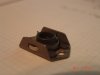
End plates were cut and tack welded in place. Before final welding, the length of the vertical section was confirmed to assure a snug fit within the existing frame on the rear of the tub.

IMG_5625.jpg


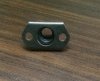
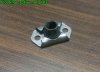
The welds on the sleeves for the 3/8” bolts were ground smooth. (Before and after shown).

IMG_5266(1).jpg


Once the two frames were completed, 3/8” holes were match drilled in the rear wall of the tub and the supports were temporarily bolted in place.

DSC_0798.JPG


Painting is being deferred for now, as additional parts are being fabricated, including the fuel tank frame.
 

Doug M

Supporter
Chuck, since you have some engineering and designs skills... How difficult would it be to design a simple removable headrest for the passenger seat? Something that removes easily when it’s just the driver and where the mount doesn’t interfere with the design, but would keep a passenger from having neck issues for the rest of their life if you happen to get rear ended while taking a friend for a ride.
 

Chuck

Supporter
Chuck, since you have some engineering and designs skills... How difficult would it be to design a simple removable headrest for the passenger seat? Something that removes easily when it’s just the driver and where the mount doesn’t interfere with the design, but would keep a passenger from having neck issues for the rest of their life if you happen to get rear ended while taking a friend for a ride.
Doug: I see no reason why it could not be done. The easiest solution would be to use a stock headrest, the kind that can be removed from the car with the two lower posts. A pair of steel tubes with an inside diameter matching the headrest posts could then be secured to the back of the tub. The headrest could be easily dropped in place when needed and removed when not needed.

There would be some details to sort out, but it seems eminently doable.
 

Chuck

Supporter
Access for Transmission, Part I

Four hex head bolts fasten the T5 transmission to the bell housing. We were unable to install the engine with the transmission attached, so the transmission will be installed after the engine is set in place. Accessing those four bolts was a challenge. Adding access openings seemed like a good solution.

Four access holes were drilled, 2 ½” diameter, to provide access to the bolts. Determining the proper location was a time consuming task but once the location was determined a pattern was made which assured proper and symmetrical placement on both sides.


DSC_0753.JPG


After the 2 ½ holes were cut they were joined with a saber saw making an oval shaped opening. This makes accessing those four transmission bolts so much easier.

DSC_0765.JPG


DSC_0810.JPG


Aluminum plates 4” x 10” x .09 were cut to cover the holes. The chassis was drilled and threaded for the attaching screws. These access panels will be concealed by the leather tunnel cover when the car is complete.

DSC_0689.JPG


More details will be posted later.
 
Last edited:

Chuck

Supporter
Access for Transmission, the Details, Part II

Drilling the 2 ½” holes with a hole saw was straightforward, once the locations were determined. The cover plates, however, required some techniques to assure proper alignment of the eight screws. With costly, modern manufacturing techniques, this is not an issue, but using simple tools in one’s garage makes it a bit more challenging. Here how we did it.

As is our habit, we started by making a pattern on grid paper. The goal was to precisely locate the eight screw holes.

IMG_5408 (2).jpg


After the two 4” x 10” aluminum plates were cut, they were taped together using masking tape. This will assure that both will be identical. Using the pattern the center point of each screws was marked with a punch as precisely as possible.

DSC_0526.JPG


Guide holes were drilled, 3/32” in diameter, using a drill press. By using the fence on the drill press table further accuracy of the hole placement was assured.

Next the pattern was taped over the 2 ½” holes. Using the pattern, two and only two, holes, 3/32” in diameter, were drilled at opposite corners. At this point the aluminum plates were set in place and secured with two clecos. Clecos are the mainstay of aircraft construction and come in handy for such projects.

DSC_0533.JPG


With the two clecos in place, the remaining holes were match drilled and a cleco placed in each, one at a time.

DSC_0547.JPG


The clecos and the panel were removed. The chassis holes were drilled out with a #30 bit, which is the size needed to tap for a 10/24 screw.

The holes on the tunnel were tapped for 10/24 screws, sixteen in total. This was a time consuming task. With the chassis holes drilled and taped, attention returned to the cover plates.

DSC_0554.JPG


Doug M

Supporter
A quick little tale on what happened to me this past week. I’ve been on other forums asking XK6 tech questions, and I get a message from someone who ended up being only 3.5 hours from me who had an XK engine he wanted gone. It was for a project that never happened, and he wanted to clear the floor space in his shop. So, for absolutely free, I now have a 1977 Series 2 XK6 engine with intake manifold, carbs, exhaust manifold, and an automatic transmission.

Obviously, work will need to be done. It has the stock Stromberg carbs, so those will get replaced with SUs most likely. Both engine and transmission will need to be rebuilt. I’m going to spend some of the winter stripping it of unneeded parts and cleaning it. Then I’ll take it to have a compression test.

Still not 100% sure if I’ll get the D Type Kit, though this bit of interesting luck has moved me more forward. Regardless, it’ll be fun to learn more about the XK6 now that I have one in front of me to study.
AF66032D-E354-456B-B8AA-16F068B69ED7.jpeg
 

Chuck

Supporter
A quick little tale on what happened to me this past week. I’ve been on other forums asking XK6 tech questions, and I get a message from someone who ended up being only 3.5 hours from me who had an XK engine he wanted gone. It was for a project that never happened, and he wanted to clear the floor space in his shop. So, for absolutely free, I now have a 1977 Series 2 XK6 engine with intake manifold, carbs, exhaust manifold, and an automatic transmission.
Doug, that is AWESOME. And you can't beat the price.

Let me know if you need anymore dimensions to confirm the auto tranny will fit.
 

Chuck

Supporter
Access for the Transmission, the Details, Part III.

With the tunnel ready for the cover plates, attention was turned to completing them.

The aluminum plates were taken back to the drill press. A countersinking tool made the job easy. This little jewel when properly set produced sixteen identically countersunk holes. After the countersinking, the center hole was drilled out to accommodate the 10/24 screws.

DSC_0559.JPG


Heat shielding, Thermo Tec Adhesive Backed Barrier, Summit Racing, THE-13590, was attached to the back of the plates after which the screw hole locations were cut out with an Xacto knife. The same heat shielding material will be used on the transmission tunnel at a later time.

DSC_0688.JPG


Now the plates can be screwed in place. All sixteen holes lined up nicely.

So much work, just to assure alignment of the screws. Job done, transmission is now setting temporarily in place with the four attachment bolts snugged.

IMG_5646.jpg
 

Neil

Supporter
Those precision aircraft countersinking tools are invaluable. Threading a fairly thin aluminum plate doesn't give you much thread engagement and, without using Loctite, you may find the screws loosening over time. I'd recommend using nut plates for engaging screws in thin sheet metal. There are two types- fixed and floating. Both types provide a prevailing torque locking mechanism.
 

Attachments

  • Nut Plate 2.jpg
    Nut Plate 2.jpg
    400.7 KB · Views: 325
  • Nut Plate 1.jpg
    Nut Plate 1.jpg
    398.7 KB · Views: 333
  • Nut Plate.jpg
    Nut Plate.jpg
    141.4 KB · Views: 328
  • Floating Nut Plate a.jpg
    Floating Nut Plate a.jpg
    71.3 KB · Views: 363

Chuck

Supporter
Neil:

Excellent tip. I have installed dozens of nut plates in the scenario you mention: thin sheet metal and composite / carbon fiber materials.

In this case the aluminum chassis which we drilled and tapped is as thick as the nuts on the nut plates and the eights screws support nothing other than the thin cover plate. If ever we have a hint that the connections are in jeopardy we can easily add nut plates 'down the road.'

When the cover plates are finally assembled a long long time from now a dab of Locktite is indeed a good idea. Thanks for the input.
 

Doug M

Supporter
Let me know if you need anymore dimensions to confirm the auto tranny will fit.

Thank you. The bell housing is 15” wide, and I’m sure that would fit. The length is probably different than the Tremec, so I’ll likely need to have a driveshaft cut to proper length. But I was expecting that would have to be done.

This transmission will be my fallback plan. I still would really like to use an overdrive transmission. The 700r4 is pretty much bulletproof (figuratively, and possibly literally). But the bell housing is 20” across. Fran indicated that he was willing to help make something work, but I fear that much modification would have to be done in the footwells and that might weaken the overall frame strength. Anyway, still researching options, but at least I have the transmission solved on a base level.
 

Chuck

Supporter
Rear Sub Frame, Part I

In previous posts the secondary rear frame which supports the fuel tank was discussed, noting that it would also support a planned sub frame. The sub frame is a noticeable detail. On the original it was part of the structure that carried the weight of the rear clip including the forty gallons of fuel. This sub frame is primarily cosmetic and not necessary for a functional D Type, unless one wants to make the rear clip removable as on the original.

Ryan was fortunate to have spent a couple of days at the Goodwood Revival in September, 2019, where he saw a host of original D Types. Yes, I was very jealous. While there he snapped a large number of pictures capturing many details not seen in the usual reference sources. These pictures of the original illustrate what will be duplicated.


Original1.jpg


original2.jpg


Original3.jpg


Original4.jpg


Not seen in these photos is the supporting bar that connects the rear bracket to the upper rear of the tub triangulating the structure. Our plan is to add a similar support by making a connection between the aft end of the secondary rear frame to the inner side of the lower rear bracket. This will make it feasible to cut the rear clip away and make it removable, as in the original, providing better access to the rear suspension and fuel system.

The plan is to use 1” diameter tube. Heim joints will be used in strategic locations to permit adjustment, although most of the visible connections will be flat plates welded to the tubes as seen in the photos of the original.
 
Rear Sub Frame, Part I

In previous posts the secondary rear frame which supports the fuel tank was discussed, noting that it would also support a planned sub frame. The sub frame is a noticeable detail. On the original it was part of the structure that carried the weight of the rear clip including the forty gallons of fuel. This sub frame is primarily cosmetic and not necessary for a functional D Type, unless one wants to make the rear clip removable as on the original.

Ryan was fortunate to have spent a couple of days at the Goodwood Revival in September, 2019, where he saw a host of original D Types. Yes, I was very jealous. While there he snapped a large number of pictures capturing many details not seen in the usual reference sources. These pictures of the original illustrate what will be duplicated.


View attachment 102700

View attachment 102701

View attachment 102702

View attachment 102703

Not seen in these photos is the supporting bar that connects the rear bracket to the upper rear of the tub triangulating the structure. Our plan is to add a similar support by making a connection between the aft end of the secondary rear frame to the inner side of the lower rear bracket. This will make it feasible to cut the rear clip away and make it removable, as in the original, providing better access to the rear suspension and fuel system.

The plan is to use 1” diameter tube. Heim joints will be used in strategic locations to permit adjustment, although most of the visible connections will be flat plates welded to the tubes as seen in the photos of the original.
Very ambitious, but you guys always come thru!
I'll have to forego the opening rear bodywork.
 

Doug M

Supporter
So are you planning an under body exhaust with a muffler in lieu of the side pipe? I might go that route myself ... I'm assuming the non muffled side pipes will be pretty loud even at a normal throttle... though it is an I6 and not a 500+ hp V8, so I could be overthinking it.
 

Chuck

Supporter
So are you planning an under body exhaust with a muffler in lieu of the side pipe? I might go that route myself ... I'm assuming the non muffled side pipes will be pretty loud even at a normal throttle... though it is an I6 and not a 500+ hp V8, so I could be overthinking it.
The rear secondary frame is used on all D Types regardless of exhaust layout. It was needed to support the weight of the rear including the 40 gallons (if memory serves me) of fuel. It also made it feasible to remove the rear clip, although that was a cumbersome process I am sure.

Regardless, my plan is under body rear exhaust. Yes, getting the noise directed out the rear should be quieter than out the side, although more objectionable for the passenger than the driver I suspect.
 

Doug M

Supporter
There’s also the risk of leg burns when the passenger exits the car after a ride, which is a strike two for my street use plans, even though the side pipes look so great.
 
Back
Top