
You are using an out of date browser. It may not display this or other websites correctly.
You should upgrade or use an alternative browser.
You should upgrade or use an alternative browser.
Chuck's Jaguar D Type Build
- Thread starter CESLAW
- Start date
Hi Chuck,
Your thread has motivated me to get a D-Type. I live in Toronto so it looks like there might be two RCR D types in Toronto!
My plan is to track the car.
Awesome progress!
The only thing better than 1 D-type in the GTA is 2!!!!!!!!
Chucks approach and accomplishments are thoroughly amazing. I really appreciate his attention to detail!
Great news Joseph! The adventure begins . . . . .Hi Chuck,
Your thread has motivated me to get a D-Type. I live in Toronto so it looks like there might be two RCR D types in Toronto!
My plan is to track the car.
Awesome progress!
Joseph, how did you choose to configure your D Type?
Battery Bracket, Part I
The battery on the original was located in top of the right forward foot well area and was plainly visible under the front clip. This was not a viable option on this reproduction since it would have required cutting a large opening into the driver’s foot well and the space would permit only a very tiny battery. So another option was needed.
The left aft side of the rear bulkhead is unused space. Moving a heavy battery to that area would also improve the balance of the car. (Yea, I know. That reason is a bit flimsy). But a properly sized battery and means of supporting it will be needed.
We used an AGM Odyssey battery on the GT40 and it has served us well, the original lasting a decade before it finally gave up the ghost. A smaller AGM Odyssey has provided excellent service in the Carbon Cub we built five years ago. The fact that they are sealed, can be mounted in any position, and will charge with the voltages put out by stock alternator voltage regulators make the selection of an AGM an obvious choice.
The Odyssey PC1100 is described as a ‘racing battery’. It is under ten inches long, less than four inches deep, and stands eight inches tall. Its ‘flat’ shape is ideal for the planned location. It is heavy.
We made a foam core board mock up, slightly larger, which is much easier to move around than a 30 pound battery. This gave us a means of determining the best location and confirmed that it would clear the suspension and other components.

The optimum location was determined and marked on the inner side of the bulkhead.

Since this is an ‘out of the way location’ access needs to be assured for replacement and connecting or disconnecting cables to the terminals. We decided to add an access port just above the battery. It will be a simple matter to reach the battery terminals from behind the passenger seat cushion. Its location can be seen in the foregoing photograph.

With a plan in place it is time to start cutting and building.
The battery on the original was located in top of the right forward foot well area and was plainly visible under the front clip. This was not a viable option on this reproduction since it would have required cutting a large opening into the driver’s foot well and the space would permit only a very tiny battery. So another option was needed.
The left aft side of the rear bulkhead is unused space. Moving a heavy battery to that area would also improve the balance of the car. (Yea, I know. That reason is a bit flimsy). But a properly sized battery and means of supporting it will be needed.
We used an AGM Odyssey battery on the GT40 and it has served us well, the original lasting a decade before it finally gave up the ghost. A smaller AGM Odyssey has provided excellent service in the Carbon Cub we built five years ago. The fact that they are sealed, can be mounted in any position, and will charge with the voltages put out by stock alternator voltage regulators make the selection of an AGM an obvious choice.
The Odyssey PC1100 is described as a ‘racing battery’. It is under ten inches long, less than four inches deep, and stands eight inches tall. Its ‘flat’ shape is ideal for the planned location. It is heavy.
We made a foam core board mock up, slightly larger, which is much easier to move around than a 30 pound battery. This gave us a means of determining the best location and confirmed that it would clear the suspension and other components.
The optimum location was determined and marked on the inner side of the bulkhead.
Since this is an ‘out of the way location’ access needs to be assured for replacement and connecting or disconnecting cables to the terminals. We decided to add an access port just above the battery. It will be a simple matter to reach the battery terminals from behind the passenger seat cushion. Its location can be seen in the foregoing photograph.
With a plan in place it is time to start cutting and building.
Looks like a great plan.
Did you consider an emergency isolation switch on the outside somewhere in the vicinity?
Did you consider an emergency isolation switch on the outside somewhere in the vicinity?
Yes, indeed. I am looking at an original style Jaguar battery cut off switch which would be mounted in the round opening between the seats on the rear bulkhead. Out of the way, partially hidden from view. Would provide another level of security in this open top car. More details coming once I have explored options.
Battery Bracket, Part II
Our first attempt was made with aluminum, nicely riveted together. Using aluminum we were able to bend the sections for a neat look with our limited collection of tools. To assure it would be strong enough, the aluminum was doubled and even tripled in some locations. Then Ryan looked at it and said ‘no.’ Aluminum fatigues and with a thirty pound battery setting in this light bracket, subjected to the vibrations of our lousy roads, it could eventually fail. Darn.

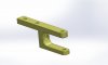
Plans for a revised bracket were drawn.
.jpg")
The bracket is made from 14 gauge steel, .0750 thick. The flat pieces were cut with a jig saw, edges smoothed with a bench sander, and tack welded together to confirm the design.
The 1 3/8” hole in the bottom is to aid in removal of the battery. Lifting it from the bracket can be awkward, so pushing upward through that opening should make it easier. Replacement of the battery will be from underneath the car; likely a two person job.
The bracket is secured to the bulkhead with four ¼” counter sunk screws.
The side brackets are connected to ¼” bolts, 4 ½” long. Half inch steel angle holds the battery in place.


The access hole on the aft bulkhead was cut and six holes drilled and tapped for 5/16” bolts. I see no need to add more than six bolts since there will be no pressure exerted against this access plate.

Remaining tasks are final welding, paint, and installation.
Our first attempt was made with aluminum, nicely riveted together. Using aluminum we were able to bend the sections for a neat look with our limited collection of tools. To assure it would be strong enough, the aluminum was doubled and even tripled in some locations. Then Ryan looked at it and said ‘no.’ Aluminum fatigues and with a thirty pound battery setting in this light bracket, subjected to the vibrations of our lousy roads, it could eventually fail. Darn.
Plans for a revised bracket were drawn.
The bracket is made from 14 gauge steel, .0750 thick. The flat pieces were cut with a jig saw, edges smoothed with a bench sander, and tack welded together to confirm the design.
The 1 3/8” hole in the bottom is to aid in removal of the battery. Lifting it from the bracket can be awkward, so pushing upward through that opening should make it easier. Replacement of the battery will be from underneath the car; likely a two person job.
The bracket is secured to the bulkhead with four ¼” counter sunk screws.
The side brackets are connected to ¼” bolts, 4 ½” long. Half inch steel angle holds the battery in place.
The access hole on the aft bulkhead was cut and six holes drilled and tapped for 5/16” bolts. I see no need to add more than six bolts since there will be no pressure exerted against this access plate.
Remaining tasks are final welding, paint, and installation.
Ian Anderson
Lifetime Supporter
Chuck
Should that battery not be rotated 180 degrees to keep the terminals away from the angle iron bracket.
All too easy to touch It on both terminals on fitting and removal.
Ian
Should that battery not be rotated 180 degrees to keep the terminals away from the angle iron bracket.
All too easy to touch It on both terminals on fitting and removal.
Ian
Thorough thought process and great execution. As usual!
Chet Zerlin
Supporter
Chuck,
I continue to be impressed with your level of planning and fabrication.
Chet
I continue to be impressed with your level of planning and fabrication.
Chet
Ian: Excellent point. Yes indeed I need to protect that bracket to minimize the risk of a short. Considering options, including reversing the battery 180 degrees per your suggestions and placing an insulating surface on the bulkhead or adding a cover on the angle iron and covering the tightening rod and wingnut. The final solution will be deferred until I pin down the type of battery connection that will be used. Appreciate your observation.Chuck
Should that battery not be rotated 180 degrees to keep the terminals away from the angle iron bracket.
All too easy to touch It on both terminals on fitting and removal.
Ian
Battery Bracket, Part III
Welding is complete. Eastwood Extreme Chassis black finished the project.

Felt strips, a quarter inch thick, were placed on the bottom. A half inch thick strip was placed on the front lower lip to keep the lower portion of the battery stable. Two thin strips were placed on the back side. This material is available from McMaster Carr.

The two tie downs use wing nuts to simplify removal. Removing the battery when the car is complete will be a challenge and likely a two person job, so anything to make the job easier is worthwhile. Each wingnut and the tie down were drilled with a 1/16” hole so they could be safety wired (which will be added later) as extra insurance against it coming loose. Overtightening the wing nuts would not be wise. A split lock washer was also used.

Washers were used between the holder and the rear wall. Nyloc nuts hold the four counter sunk bolts in place. Remaining are the connections to the battery. At that time we will explore options to minimize the risk of the positive terminal being shorted to a grounded connection.

Welding is complete. Eastwood Extreme Chassis black finished the project.
Felt strips, a quarter inch thick, were placed on the bottom. A half inch thick strip was placed on the front lower lip to keep the lower portion of the battery stable. Two thin strips were placed on the back side. This material is available from McMaster Carr.
The two tie downs use wing nuts to simplify removal. Removing the battery when the car is complete will be a challenge and likely a two person job, so anything to make the job easier is worthwhile. Each wingnut and the tie down were drilled with a 1/16” hole so they could be safety wired (which will be added later) as extra insurance against it coming loose. Overtightening the wing nuts would not be wise. A split lock washer was also used.
Washers were used between the holder and the rear wall. Nyloc nuts hold the four counter sunk bolts in place. Remaining are the connections to the battery. At that time we will explore options to minimize the risk of the positive terminal being shorted to a grounded connection.
Consider using fiberglass angle versus steel for the hold down.
Then use rubber grommets at the heads of the hold down bolts to isolate them from the metal of the battery box. Properly sized, they also hold the bolts in place while you blindly fit the angle, washer and wi gmut in place.
This is a beauty with the body off, but likely an invisible challenge with the body, fuel tank, suspension etc. In place
Alternator Bracket, Part IV
The final welding was completed and the bracket primed and painted with Eastwood Extreme Chassis Black. I have learned that this primer and paint needs a long time to dry. I let it dry for a week before doing any serious work with the part, although once thoroughly dry it has proven very durable.

The bracket and alternator were bolted in place. Measurements were taken to determine the correct size pulley belt. An alternator belt 40 3/8” inches long and 1/2 inch wide was used. NAPA XL 9400. The belt length is critical since there is minimal adjustability with this set up. Indeed it was necessary to remove the alternator pulley to install the belt. With the belt in place and the tensioner tightened, there was more than an inch of clearance between it and the adjoining chassis so there should not be an issue of interference between the chassis with engine movement during those hard runs down the Mulsanne straight.


The final welding was completed and the bracket primed and painted with Eastwood Extreme Chassis Black. I have learned that this primer and paint needs a long time to dry. I let it dry for a week before doing any serious work with the part, although once thoroughly dry it has proven very durable.
The bracket and alternator were bolted in place. Measurements were taken to determine the correct size pulley belt. An alternator belt 40 3/8” inches long and 1/2 inch wide was used. NAPA XL 9400. The belt length is critical since there is minimal adjustability with this set up. Indeed it was necessary to remove the alternator pulley to install the belt. With the belt in place and the tensioner tightened, there was more than an inch of clearance between it and the adjoining chassis so there should not be an issue of interference between the chassis with engine movement during those hard runs down the Mulsanne straight.
Steering, Part I
Our kit came with the steering rack and inner tie rods but not the outer tie rods and steering arms, so coming up with a suitable design was our next project. In order to achieve the desired geometry the rack needed to be extended on each side. Fortunately 2” extenders are available, which is very close to the dimensions we were seeking. Heidts Rack and Pinion Extension Kit MP-037-4, available from Summit. (Replacing the rack was not a viable option).

Tie rods. A couple of different approaches were explored. Regardless, two items will be required which ever solution is chosen. First, the rack and pinion extensions will be required and, second, the steering arms will need to be fabricated. Although the connection point between the steering arm and outer tie rod will depend on which option is chosen, the total length of the steering arms will be the same for each. Following is the first option we explored.
Option 1. One can use the inner tie rod provided by RCR by using a compatible outer tie rod, threaded ½-20 . We tested a pair of QA1 rod ends which work well and cost less than $40 for the pair. This is the least expensive solution. Summit Racing part number QA1-PCYFR8T.
When installing the outer tie rods safety washers were used. Rather than aluminum, steel safety washers were ordered. (The Chassis Shop is a good source.) https://secure.chassisshop.com/partdetail/C73-466-2/ The design of the outer tie rod and the use of these safety washers provide the necessary clearance.

Here is a picture of this outer tie rod in place, final assembly.

The concern with this option is the single shear attachment point to the steering arm with a straight ½” bolt. I am interested in any comments regarding this approach. A better option may be a tapered shank extending into the steering arm with a half inch connection for this outer tie rod, but we were unable to find one with suitable dimensions.
We are exploring another option for the tie rod connection. Unfortunately a critical part has been on back order for several weeks, so it will be the subject of a future post.
Steering Arm. The original D Type steering arms were essentially a straight bar extending forward from the upright. We duplicated this approach, ordering a steel bar 1” x 5/8” x 24”, from McMaster-Carr. Part 8910K718. The bar was cut and holes were drilled per the specs shown.

To assure a good fit, the holes were drilled in increments starting with a 1/16” and finally ending with a step drill. The result was reasonably precise, clean holes. The steering arm will need a coat of paint, but that will be deferred until we can explore another option for the tied rod to steering arm connection. In the meantime we now have fully functional steering, subject to some minor details that will be addressed.
Our kit came with the steering rack and inner tie rods but not the outer tie rods and steering arms, so coming up with a suitable design was our next project. In order to achieve the desired geometry the rack needed to be extended on each side. Fortunately 2” extenders are available, which is very close to the dimensions we were seeking. Heidts Rack and Pinion Extension Kit MP-037-4, available from Summit. (Replacing the rack was not a viable option).
Tie rods. A couple of different approaches were explored. Regardless, two items will be required which ever solution is chosen. First, the rack and pinion extensions will be required and, second, the steering arms will need to be fabricated. Although the connection point between the steering arm and outer tie rod will depend on which option is chosen, the total length of the steering arms will be the same for each. Following is the first option we explored.
Option 1. One can use the inner tie rod provided by RCR by using a compatible outer tie rod, threaded ½-20 . We tested a pair of QA1 rod ends which work well and cost less than $40 for the pair. This is the least expensive solution. Summit Racing part number QA1-PCYFR8T.
When installing the outer tie rods safety washers were used. Rather than aluminum, steel safety washers were ordered. (The Chassis Shop is a good source.) https://secure.chassisshop.com/partdetail/C73-466-2/ The design of the outer tie rod and the use of these safety washers provide the necessary clearance.
Here is a picture of this outer tie rod in place, final assembly.
The concern with this option is the single shear attachment point to the steering arm with a straight ½” bolt. I am interested in any comments regarding this approach. A better option may be a tapered shank extending into the steering arm with a half inch connection for this outer tie rod, but we were unable to find one with suitable dimensions.
We are exploring another option for the tie rod connection. Unfortunately a critical part has been on back order for several weeks, so it will be the subject of a future post.
Steering Arm. The original D Type steering arms were essentially a straight bar extending forward from the upright. We duplicated this approach, ordering a steel bar 1” x 5/8” x 24”, from McMaster-Carr. Part 8910K718. The bar was cut and holes were drilled per the specs shown.
To assure a good fit, the holes were drilled in increments starting with a 1/16” and finally ending with a step drill. The result was reasonably precise, clean holes. The steering arm will need a coat of paint, but that will be deferred until we can explore another option for the tied rod to steering arm connection. In the meantime we now have fully functional steering, subject to some minor details that will be addressed.

")
Chris Kouba
Supporter
Can you use a ball joint for that outer end? I have a tapered reamer you can borrow to set it into that steering arm.
You may need to shift your rack height slightly if it's all set up as desired but that depends on the dimensions of the ball joint.
I know they're not as sexy as heims, but they would probably be more period correct (yes, I realize they'd be located right next to CNC'd uprights).
You may need to shift your rack height slightly if it's all set up as desired but that depends on the dimensions of the ball joint.
I know they're not as sexy as heims, but they would probably be more period correct (yes, I realize they'd be located right next to CNC'd uprights).
Yes indeed a ball joint is an excellent idea. Even found one and ordered it, but after waiting months for it to arrive I gave up. Other downside with a ball joint is it makes adjustment for bump steer a bit more complicated. I am now looking at a 'bump steer kit' as an option - which has the tapered stud and would be nicely adjustable (similar to what I used on the GT). It will require a specific inner tie rod which has been on order now for three weeks.Can you use a ball joint for that outer end? I have a tapered reamer you can borrow to set it into that steering arm.
You may need to shift your rack height slightly if it's all set up as desired but that depends on the dimensions of the ball joint.
I know they're not as sexy as heims, but they would probably be more period correct (yes, I realize they'd be located right next to CNC'd uprights).
Thanks for the offer on the tapered reamer. I have one ready to go as soon as the parts get here.
Between shut downs (which have greatly increased demand for home builders like us) and Chinese issues parts are sometime hard to get.
Similar threads
- Replies
- 1
- Views
- 459
- Replies
- 1
- Views
- 2K