Dan's GT-R Build

Dan

Supporter
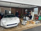
As some of you may know, I bought Jim B's GT-R kit, which was originally Tom L's kit from Buffalo. When I took ownership, almost nothing had been done to the car. What I actually bought was a giant trailer full of parts, loosely resembling a car.

To pick it up, my brother and I embarked on a 6,000-mile round-trip journey from Allentown, PA to Portland, Oregon. The trip included 65–75 mph crosswinds, plenty of questionable decisions, and a generous dose of "liquid encouragement" that probably influenced the purchase more than I'd like to admit.


At the time, I thought I was taking home a project that would take six months to finish. Turns out… well, let’s just say I was a little optimistic.
 

Attachments

  • IMG_2313.JPEG
    IMG_2313.JPEG
    516.6 KB · Views: 33

Dan

Supporter
I’ve been diving deep into GT-R build logs—reading everything I can get my hands on. I even printed and bound a personal library of logs for reference. One of the early improvements I tackled was the front suspension mod based on Kurtis’ guidance, which helped eliminate that awkward front-end wheel spacer. Huge upgrade.

However, I found myself at a unsure: should I move the suspension mount all the way up, as some recommend, or leave it in its original position? After weighing the pros and cons of each approach, I landed on what felt like the most “scientific” answer—splitting the difference. That meant designing my own top mounting bracket. I’ve never done that before.

So naturally, I went out and bought a milling machine, bandsaw and other milling equipment. (Thanks, Jon, for the nudge.) I fired up the 3D printer and let my credit card stretch its legs on McMaster-Carr. What I came up with is something I’m pretty proud of:
  • No more aluminum spacer or that top-threaded hole workaround
  • No cutting into the front aluminum clip
  • Bracket matches the original in thickness and radii
  • Started with a chunk of 316 stainless steel rectangular tubing with 0.18" wall thickness
  • My horizontal bandsaw nearly died (yes, I had the wrong blade—but I wasn’t buying another)
The original bracket spacing between mounting screws was 2.16". The upper relocation mod would have moved it the full 2.16" upward, but my solution moves the bracket up halfway—just 1.08"—and shifts it outward by 1.0". Clean, solid, and reversible.

One part down. 499 to go.
 

Attachments

  • IMG_2989.JPEG
    IMG_2989.JPEG
    201.7 KB · Views: 26
  • IMG_2990.JPEG
    IMG_2990.JPEG
    192.9 KB · Views: 16
  • IMG_2991.JPEG
    IMG_2991.JPEG
    171.2 KB · Views: 16
  • IMG_2985.JPEG
    IMG_2985.JPEG
    375 KB · Views: 14
  • IMG_2986.JPEG
    IMG_2986.JPEG
    436.1 KB · Views: 18
  • IMG_2987.JPEG
    IMG_2987.JPEG
    380.9 KB · Views: 20
  • IMG_2988.JPEG
    IMG_2988.JPEG
    315.7 KB · Views: 25
Nice Work Dan. Great solution.

A couple things to keep in mind:

1- You will likely find, like others that have done this mod, that your camber is way off in the negative direction. Too far off to safely adjust the rod end on top of the upper a arm. To remidy this situation you will need to put spacers behind the upper rod ends and the upper a-arm. You may also need the shims used previously to ensure the clocking works out once tightening. You can find this fix further into Kurtis's thread.
2-Double check the steering tie rod stand off. If it is not short enough it will cause the bolt to rub against the inside of your rim. Don't ask me how I know this. :)

I would add another zero to the 499 number left to go. I think I have surpased 4990 now. Keep at it.

My 2 cents worth....
 

Attachments

  • 2 (1).jpg
    2 (1).jpg
    198.3 KB · Views: 24
  • Spacers.jpg
    Spacers.jpg
    59.5 KB · Views: 27

Dan

Supporter
Great advice. Thank you! Would there have been the same issue with the camber with the original helm joints? I have no problem adding the spacers. Once I put the wheels on, I can check the camber.
 

Dan

Supporter
I get it. I’ve move the mounting point up. That will increase the camber likely beyond an adjustable point. I’m going to put the car together and see where my camber winds up. I’m guessing 1-1.5 degrees for a street car.
 
I'm not sure if the problem exists before modification. But I did see one of Alan's videos on alignment and it appeared he ran out of adjustment while filming. I can't remember if his video was a GT-R or SLC. I'm sure it is not a big deal now, as you will be adding weight as you build. I would just get it close for now knowing it will settle a bit in the future.
 

Randy V

Moderator-Admin
Staff member
Admin
Lifetime Supporter
Congratulations on your new project Dan!

I get it. I’ve move the mounting point up. That will increase the camber likely beyond an adjustable point. I’m going to put the car together and see where my camber winds up. I’m guessing 1-1.5 degrees for a street car.

While I’ve not built or set up a GTR, I have done countless race cars and street cars. I would suggest no more than -.5° negative camber for the street.
The reasons are as follows regarding too much negative camber -
1) The car will be just a little more evil to drive - particularly on grooved roads and it will want to dart much faster - much in the same way that more than 1/8” toe-out will cause.
2) Reduced straight-line braking performance as your tire loading will not be even across the face of the tread.
3) Reduced traction in the wet.
4) Accelerated tire wear.
 

Dan

Supporter
Thank you Randy. Luckily, I have already thrown away a lot of money, or as I justified to my wife, "invested" in alignment equipment for my race car. I have Hubstands, string kits and corner scales, etc. I remember at one race, I quickly changed the camber on the rear wheels and unexpectedly put just a 1/16" total toe OUT in the rear. I thought I was going to die on the track. I appreciate your advice. I have never set up a street car's alignment. But this will eventually be my first.
 
Back
Top