Jim's RCR GT-R build

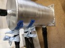
I am looking for the thread size for the pickup and return bung in the RCR GT-R tank. I have the RCR fuel system but those did not come with it. I know one is 1/2" NPT, but the other seems different.
I also wanted to see what others have used for the fitting and in tank tubing for the pickup and return lines.
 
I was able to get the trans adapter plate installed. it was very tight fit. I removed it and got all the bolts started then just tightened the bolts in a cris-cross pattern in small increments to ease it on.
after that the flywheel and clutch went right on.
I used a universal clutch alignment tool and it seemed to work well. I will see when we install the trans
 

Neil

Supporter
I was able to get the trans adapter plate installed. it was very tight fit. I removed it and got all the bolts started then just tightened the bolts in a cris-cross pattern in small increments to ease it on.
after that the flywheel and clutch went right on.
I used a universal clutch alignment tool and it seemed to work well. I will see when we install the trans
"I will see when we install the trans"
If you used a plastic alignment tool, it won't be fun.
 

Neil

Supporter
This is the one I used (it was cheaper when I got it)
I have a few other projects coming up that I can use it for.
That is a good one. This is the POS to avoid:

Clutch Alignment Tool- Plastic.jpg
 
I went with the boss intake which has tons of room to reverse. I had to extend the MAF connector and didnt want to cut the wiring. I found this as cheap extender, I just had to shave off a small part of plastic. https://www.amazon.com/dp/B097SK52QC
I have the RCR Fuel system and I am working on the layout. I have 2 different diagrams I found in these forums. There are a couple main differences and I was wondering which is correct.
1. one uses the low pressure pump(Bosch) from the main tank the other uses the high pressure pump (Walbro) and then the opposite for the pump to the fuel rail. I assumed the high pressure pump would feed the fuel rail but....
2. one has the filter before the pump
 

Attachments

  • Fuel system compare.jpg
    Fuel system compare.jpg
    140.5 KB · Views: 103
  • boss intake side view.jpg
    boss intake side view.jpg
    335.3 KB · Views: 89

Ken Roberts

Supporter
The low pressure fuel filters job is to protect the fuel pumps from contaminants in the tank. Therefore it should be located before the LP pump. Here is how I would run the fuel system……..
image.jpg
 
Last edited:

Ken Roberts

Supporter
I think the Bosch pump is intended to be the high pressure pump and the Walbro as the low pressure pump. In the past there was a bit of controversy/discussion over the Walbro pump. It only needs to be a low pressure pump and RCR was shipping out high pressure pumps. There is no regulator control on the low pressure pump so the pump will flow a ton of fuel (Volume). A high pressure pump is not needed. A low pressure pump will also have less current draw and possibly run quieter.

Modern OEM fuel injection engines are not vacuum referenced. The regulator is located in the fuel tank. The fuel tables/trims are modified in these applications. Aftermarket fuel injection systems might be vacuum referenced, or you might have a choice. Keep this in mind because the fuel regulator vacuum tube should be left open if the system is not vacuum referenced. Aeromotive states this in their installation documents.
 
Last edited:
I wonder if this is thinking "OEM in tank 'low' pressure fuel pump" then an inline filter before the Surge tank and high pressure pump. Because that's honestly the only reason I'd think to put the filter after one pump. (most In-tank pumps have some kind of filter plus their slosh-sock)
 
@KENS80V , thanks for the reply, The system didnt come with and 8AN fittings/hose, but I just ordered the 8AN parts to follow your suggestion . The system included 10AN parts and both diagrams I have show 10AN fittings/hose from the bottom of the surge tank (10AN outlet). Any thoughts on that?
 

Ken Roberts

Supporter
I have no idea why the bottom bung on the surge tank would be a 10AN size. I could see a high horsepower build possibly requiring a 8AN bung.
 
I made all my hoses and hooked them up. I decided to bench test for leaks. Good news no leaks, bad news is that the Walbro pump is dead new out of the box. It came with my RCR fuel system. I will reach out to RCR, but I am guessing I am out of luck and on my own since it was purchased 2 years ago with the GT-R.
If I am on my own to replace should I just buy the same make/model or get something else that might be better?
1000003298.jpg
 
Okay now that's a really smart idea; a jig for testing outside the car.
Thanks. It was easy to find a couple leaks and I made a couple layout mistakes while mounting everything. I will stay with this to support my first start then use it as a pattern for the final aluminum mount.
next is temp cooling for the first start then the control pack
 
I've never bench tested, but I did run a pair of wires across the garage to power the pump for 10 minutes while I looked over every inch of the Cobra.

May be a good way to test your hose makeup skill, but you need to test again in the car to be sure you have every joint torqued to no leaks.
 
the lift tank has 3 inlet/outlets all in line, so when I had a leak it was hard to tell which was actually leaking, so I did this to make it easier to locate
 

Attachments

  • test tank.jpg
    test tank.jpg
    465.5 KB · Views: 55

Ken Roberts

Supporter
Edit the image again by rotating it to a different position (like upside down) and then save it. Edit it one more time by rotating it to the correct position then save it, then post it. That usually works for me.
 
Back
Top