Darius - RCR GT40 MK1 Build

Darius Rudis

Supporter
Darius,

Which wiring kit are you installing?

Also did you get an answer as to how to hook up the three wire sender to the two wire fuel gauge? I've got the same issue...

Thanks!
Chet
Sorry for delayed response, was away on vacation snowmobiling...
The 3-wire fuel sender was alredy explained. (I also got same confirmation from Vendor, so that is correct).

As for wiring "kit"... after being TREMENDOUSLY frustrated with Painless issues... I created my own from scratch.
My fuseboxes were 2 blocks: 1-key-on and 1-always-on.
Then run the 'small voltage/amps" switch to a relay panel, and those relays are good for 30A. So the entire car runs 5A fuses EVERYWHERE, running wires end-to-end. Then, 30A short run wires with 10g to fuel pumps / headlights / fans...

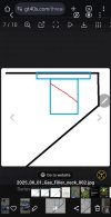
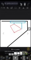
Temporary photo - fusebox setup (crimped wires are getting new heat-shrink fittings, and ALL the fuses will be 5A, when package arrives):
1740402824914.png

https://www.summitracing.com/parts/SUM-900357

1740403272663.png

(yes gromets to go thru firewall... I know)

Auto Rod Corporation:
https://www.autorod.net/product/arc-rc8/#

The turn-signal wiring block:
https://www.autorod.net/product/new-arc-tsm-1-turn-signal-module/

1740403425497.png
 

Chet Zerlin

Supporter
Thanks Darius. That's a very interesting setup! I'm having similar issues trying to decipher the "EZ Wiring" kit that came from RCR. As I noticed in several posts on this forum there is nothing EZ or Painless about any of those kits;)

I really like the way you separated the "key-on" from the "always on" wiring into two separate fuse boxes. Makes perfect sense. Looks like you used the labeled wires from your "Painless" kit?

Is that 8 relay board mounted in the battery compartment on the right side of the motor? In an early picture of your cockpit I noted two relays mounted on the chassis in back of the dash. Were those eliminated by the two relay boards or did you still need them?

Chet
 

Darius Rudis

Supporter
Thanks Darius. That's a very interesting setup! I'm having similar issues trying to decipher the "EZ Wiring" kit that came from RCR. As I noticed in several posts on this forum there is nothing EZ or Painless about any of those kits;)

I really like the way you separated the "key-on" from the "always on" wiring into two separate fuse boxes. Makes perfect sense. Looks like you used the labeled wires from your "Painless" kit?

Is that 8 relay board mounted in the battery compartment on the right side of the motor? In an early picture of your cockpit I noted two relays mounted on the chassis in back of the dash. Were those eliminated by the two relay boards or did you still need them?

Chet
Tried both EZWiring and Painless kits, tried looking at both and NEITHER would do what I wanted...
So literallt just cut off all the wires from fuseblocks, and used all the pre-labeled wires.

The 8-relay in rear battery compartment is labeled for its purposes.
The 4-relay next to fuseblocks is for radiator/headlights/highbeams/foglights (could'a used a 5th for horn...).

The passenger dashboard relays are from Vintage Air kit, for the A/C & Heat.

Separating Hot & Cold fuseblocks - accomplished with ignition key. Since everything is < 5A fused, the key has almost no load.
The main 2G battery wires to/from starter, and 6G wires from battery to fuseblocks:
1740579030693.png


Trying to get the kits to work:
1740577755874.png


The nightmare:
1740577845061.png


Leftovers after all wiring completed:
1740578169438.png
 
Last edited:

Darius Rudis

Supporter
About to put the car on a rack, and get my first paid-for alignment.

Do these washers look correct (front castor)?
1745853396973.png


According to RCR Specs:


Initial Alignment Settings
LF
RF
- 1/32​
Toe​
- 1/32​
-0.90 to -1.00​
Camber​
-0.90 to -1.00​
+ 2.5 to + 5.00​
Caster​
+ 2.5 to + 5.00​
LR
RR
- 1/32​
Toe​
- 1/32​
-0.90 to -1.00​
Camber​
-0.90 to -1.00​
+ 5.00 to + 8.00​
Caster​
+ 5.00 to + 8.00​


Neil

Supporter
About to put the car on a rack, and get my first paid-for alignment.

Do these washers look correct (front castor)?
View attachment 147042

According to RCR Specs:


Initial Alignment Settings
LF
RF
- 1/32​
Toe​
- 1/32​
-0.90 to -1.00​
Camber​
-0.90 to -1.00​
+ 2.5 to + 5.00​
Caster​
+ 2.5 to + 5.00​
LR
RR
- 1/32​
Toe​
- 1/32​
-0.90 to -1.00​
Camber​
-0.90 to -1.00​
+ 5.00 to + 8.00​
Caster​
+ 5.00 to + 8.00​


2,5 degrees? That looks like a very small amount of caster.
 

Randy V

Moderator-Admin
Staff member
Admin
Lifetime Supporter
RCR40 I built had something like 5.5° positive caster with the lower control arms shimmed all the way forward and the upper control arms shimmed all the way rearward.
 

Neil

Supporter
RCR40 I built had something like 5.5° positive caster with the lower control arms shimmed all the way forward and the upper control arms shimmed all the way rearward.
When I built my Black Mirage for running at Bonneville, I made the front wheel caster what I thought was OK for high speed stability. John Horsman asked me how much caster I built into my front suspension and I replied 7 degrees. I said "That sounds about right". It was stable at speed when I did get a chance to run on the Salt.
 

Randy V

Moderator-Admin
Staff member
Admin
Lifetime Supporter
When I built my Black Mirage for running at Bonneville, I made the front wheel caster what I thought was OK for high speed stability. John Horsman asked me how much caster I built into my front suspension and I replied 7 degrees. I said "That sounds about right". It was stable at speed when I did get a chance to run on the Salt.
Sounds right! When I set up our racecars, I usually ended up between 6.5 and 7° and if aero was right, we were quite stable…
 

Brian Kissel

Staff member
Admin
Lifetime Supporter
If one wanted more caster (up to 7degrees) than was allowed by Randy's way of shimming, couldn't one just fabricate new control arm mounts?? Just by offsetting the mount hole locations by perhaps .200 it would seem that you could more easily get the caster you want. And it would allow to go back the other way as well.I would CNC these out of billet to control their accuracy. Just thinking out loud here.

Regards Brian
 

Randy V

Moderator-Admin
Staff member
Admin
Lifetime Supporter
If one wanted more caster (up to 7degrees) than was allowed by Randy's way of shimming, couldn't one just fabricate new control arm mounts?? Just by offsetting the mount hole locations by perhaps .200 it would seem that you could more easily get the caster you want. And it would allow to go back the other way as well.I would CNC these out of billet to control their accuracy. Just thinking out loud here.

Regards Brian
I think I’d probably weld up the holes that the upper brackets are bolted to and drill new holes about 1/4” further rearward. Perhaps find some heim joints with thinner balls?
 

Brian Kissel

Staff member
Admin
Lifetime Supporter
CNC ing new mounts would be easier for me and I would still have the stock mounts just in case. Just thinking as I don’t have the car yet. Sorry for the thread drift Darius.

Regards Brian
 

Randy Folsom

Supporter
My understanding is that if the car will be primarily street, then 5^, but if the priority is track performance, then 6^. RCR recommends a compromise of 5.5^. The more caster, the greater the steering wheel effort, especially at low speeds, i.e., parking. That extra effort can reduced with a power steering unit from Flaming River or similar. I settled on 5.3^, but that had more to do with getting the wheel base right and centering the tires in the fender arches.
 

Darius Rudis

Supporter
My understanding is that if the car will be primarily street, then 5^, but if the priority is track performance, then 6^. RCR recommends a compromise of 5.5^. The more caster, the greater the steering wheel effort, especially at low speeds, i.e., parking. That extra effort can reduced with a power steering unit from Flaming River or similar. I settled on 5.3^, but that had more to do with getting the wheel base right and centering the tires in the fender arches.
I am at the catch-22 point...
Setting the body alignment, and centering onto the wheels. Also setting the wheel alignment, to center the body...
Shooting at BOTH targets at same time.
+/- a few degrees of caster isnt going to move the wheel fore/aft very much, so I think I am close enough.

Here is my current point (doors literally set on, no hinges, just for photo. Hurry and take photo, before they fall off)
1746101457195.png


1746101568213.png

1746101586847.png
 

Randy V

Moderator-Admin
Staff member
Admin
Lifetime Supporter
My sill covers needed to be shifted all the way rearward to start the body alignment process over again - once I had the front end rough-aligned. The positive caster shifts the spindle rearward a little ways.
 

Randy V

Moderator-Admin
Staff member
Admin
Lifetime Supporter
Are they all the way up against the front edge of the alloy chassis? I couldn’t tell from your photos. My tires rubbed those sill covers when turning them, so that’s how I found out.
 
Back
Top