Don's Mk IV Build

Status
Not open for further replies.

D. Nye

Lifetime Supporter
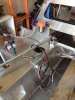
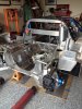
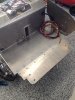
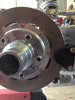
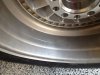
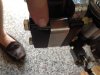
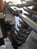
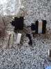
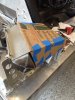
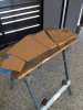
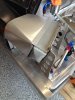
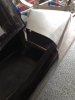
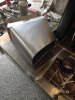
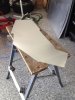
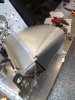
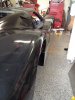
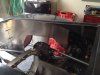
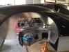
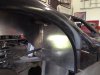
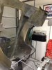
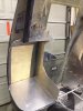
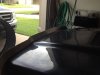
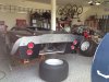
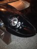
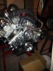
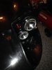
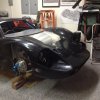
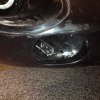
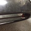
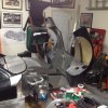
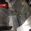
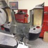
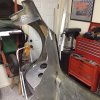
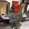
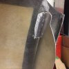
More work completed this weekend. I removed the engine to complete the rear brake line install and e-brake cables. I continue to install parts as I get them, see attached pictures.

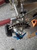
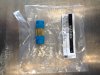
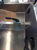
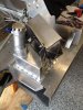
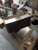
One thing many people may not know about these cars is they had no radiator cap used as a pressure relief. They used a inline pressure relief valve which is very hard to find. For those thinking of building a car like this I'll save you a few days by showing you a part number from Speedway.

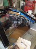
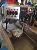
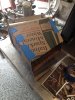
Wiring is installed in the car and waiting to terminate when I'm closer to having the front and rear clips installed.
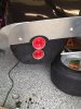
 

Attachments

  • 001.JPG
    001.JPG
    382.9 KB · Views: 683
  • 002.JPG
    002.JPG
    447.5 KB · Views: 519
  • 003.JPG
    003.JPG
    301.9 KB · Views: 486
  • 004.JPG
    004.JPG
    291.4 KB · Views: 478
  • 008.JPG
    008.JPG
    338.8 KB · Views: 459
  • 005.JPG
    005.JPG
    327.2 KB · Views: 411
  • 006.JPG
    006.JPG
    289.8 KB · Views: 507
  • 007.JPG
    007.JPG
    202.1 KB · Views: 459

D. Nye

Lifetime Supporter
As a car builder you can’t be faint of heart because there will always be challenges every step of the build. The optimism in you may believe the parts supplied with the kit would bolt on and you never have to look back. The pessimism believes nothing will fit without modification. I’m turning in to a pessimist.

Case in point is the simple task of installing emergency brakes. The job is straight forward, locate the e-brake caliper at three o’clock position, mark mounting holes, drill and tap aluminum upright and mount bracket. First thing I found was the caliper would not slip over the brake rotor. RCR supplies a new spacer which makes the caliper wider to fit over the oversized rotor however for whatever reason, the spacer sizing or Wilwood making the pads thicker, you must sand a little off the brake pad to get the caliper to slip on to the rotor. Once on you find the adjustment set screw is to long because it’s hitting the coil over shock spring. So you find a new set screw that misses the spring. At this point you mount the cables which again you think is straight forward task, all I can say is if you are building a Mk IV don’t follow the instructions for a Mk I. If you do you find the cables will be short and you will be making a new cable bracket to mount on to the caliper and if you are using vintage 15” racing tires that are nice and fat, sidewalls pillow out, you will be relocating the cable holding bracket to the chassis.

After all this you think to yourself, optimism kicking in again, cool looks good, until you mount the tires and find the caliper is hitting the inside rim of those expensive turbine wheels. So off comes the caliper and belt sander gets a taste of aluminum again removing about ten thousands. Re-mount the caliper and hook up everything, mount wheel and spin the wheel to find you have finally got the e-brakes mounted.

You think to yourself, I now know why it takes years for some people to build cars.

Work continues!
 

Attachments

  • E-Brake Parts.JPG
    E-Brake Parts.JPG
    346.2 KB · Views: 397
  • E-Brake Fit 2.JPG
    E-Brake Fit 2.JPG
    191.5 KB · Views: 447
  • 003.JPG
    003.JPG
    211.5 KB · Views: 440
  • 001.JPG
    001.JPG
    199.2 KB · Views: 446
  • 002.JPG
    002.JPG
    228.7 KB · Views: 498

Terry Oxandale

Skinny Man
And why is it we love to do this? Great post, and a snapshot of my life in the garage.

As a car builder you can’t be faint of heart because there will always be challenges every step of the build. The optimism in you may believe the parts supplied with the kit would bolt on and you never have to look back. The pessimism believes nothing will fit without modification. I’m turning in to a pessimist.

Case in point is the simple task of installing emergency brakes. The job is straight forward, locate the e-brake caliper at three o’clock position, mark mounting holes, drill and tap aluminum upright and mount bracket. First thing I found was the caliper would not slip over the brake rotor. RCR supplies a new spacer which makes the caliper wider to fit over the oversized rotor however for whatever reason, the spacer sizing or Wilwood making the pads thicker, you must sand a little off the brake pad to get the caliper to slip on to the rotor. Once on you find the adjustment set screw is to long because it’s hitting the coil over shock spring. So you find a new set screw that misses the spring. At this point you mount the cables which again you think is straight forward task, all I can say is if you are building a Mk IV don’t follow the instructions for a Mk I. If you do you find the cables will be short and you will be making a new cable bracket to mount on to the caliper and if you are using vintage 15” racing tires that are nice and fat, sidewalls pillow out, you will be relocating the cable holding bracket to the chassis.

After all this you think to yourself, optimism kicking in again, cool looks good, until you mount the tires and find the caliper is hitting the inside rim of those expensive turbine wheels. So off comes the caliper and belt sander gets a taste of aluminum again removing about ten thousands. Re-mount the caliper and hook up everything, mount wheel and spin the wheel to find you have finally got the e-brakes mounted.

You think to yourself, I now know why it takes years for some people to build cars.

Work continues!
 

D. Nye

Lifetime Supporter
I'm waiting for front end parts so have been busy working on other areas of the car while I wait.

The oil coolers are mounted and thought I would share how I made the air intakes to fit. I first cut and tape a cardboard template of what fits the car. Transfer outline to sheet metal, cut and start bending. I would like to find someone with a bead roller so I can incorporate a wire in the leading edge of the air scoop. Other than that I think it’s looking close to the originals, see attached photos. The last picture is the original J7 car.


Don
 

Attachments

  • 814.JPG
    814.JPG
    342.7 KB · Views: 437
  • 815.JPG
    815.JPG
    317.4 KB · Views: 382
  • 816.JPG
    816.JPG
    296.2 KB · Views: 348
  • 817.JPG
    817.JPG
    260.1 KB · Views: 392
  • 818.JPG
    818.JPG
    272.3 KB · Views: 359
  • 821.JPG
    821.JPG
    323.9 KB · Views: 338
  • 822.JPG
    822.JPG
    320.7 KB · Views: 337
  • 823.JPG
    823.JPG
    269.8 KB · Views: 365
  • 824.JPG
    824.JPG
    260.8 KB · Views: 360
  • 825.JPG
    825.JPG
    326.8 KB · Views: 440

D. Nye

Lifetime Supporter
There is something sexy when you finely see the tail lights installed. I spent a minimum of 6 hours removing the glue from all the packing tape this weekend. RCR uses some good tape!

Got the front and rear suspension setup and body panels are mounted and have moved on to installing all the inner wheel well panels, latches, air ducts, etc.


I really dislike body work but must be done. Looking forward to the day I can get back to the mechanical, electrical and plumbing work and hear this big 7 liter take it's first breath of air.


Just living the dream!
 

Attachments

  • 001.JPG
    001.JPG
    350.4 KB · Views: 506
  • 002.JPG
    002.JPG
    320.9 KB · Views: 481
I like the tail lights Don! Its funny that they used ones from a Chevy Corvair, still with the spoiler makes the back end look good. Nice work as always................................m
 

D. Nye

Lifetime Supporter
Thanks, hows your car coming? It's nice to know someone else with a Mk IV. Got the engine installed yet?
 
Got the proper chassis! yeah! put all the suspension on and set the engine in to get the axle lengths they are ordered making fast progress need to make some mods for the engine fit, it has taken two years to get 99% of the stuff but we have almost all of it so we should roll pretty fast. I give rcr credit the chassis although took forever is a work of art yours motivates us keep the pictures coming thanks Don...................m
 

D. Nye

Lifetime Supporter
I have many projects going on all over the car but thought I would share some pictures of the rear inner finder wells I’m about to glue in. I feel like I’m an epoxy adhesive expert after doing all the research on different adhesives. I’ll clean up the edges before final assembly but I like how they are looking. The parts are cut for the front fenders and I’ll move on to the front once I have the rear complete. The front inner fender wells will form the base for making the front have a hinged section like the rear. Both front and rear clam shells will get a coat of black under coating once I’m through cutting holes.

I also made a new rear spoiler to look like the HM cars. I like the detail of the raised section to follow the body line.

I removed the firewall and made a copy out of 1/8” plate so I can make a sound/heat sandwich and have the look of aluminum from the engine bay and from the inside but giving me some sound attenuation and try and keep the engine heat out of the cockpit. The last part of this puzzle is if I will get a glass rear window cut or use the Plexiglas window provided. From what I have read the glass is recommended for sound attenuation.

It’s been really hot and I can only work about 2 hours at a time before needing a break but work continues.

Don
 

Attachments

  • 012.JPG
    012.JPG
    195.5 KB · Views: 392
  • 013.JPG
    013.JPG
    243.2 KB · Views: 408
  • 014.JPG
    014.JPG
    210.6 KB · Views: 488
  • 016.JPG
    016.JPG
    319.8 KB · Views: 403
  • 017.JPG
    017.JPG
    319.8 KB · Views: 406
  • 015.JPG
    015.JPG
    190.1 KB · Views: 357
  • 011.JPG
    011.JPG
    297.5 KB · Views: 481

Howard Jones

Supporter
Italian sparking water, right on pizon! I like to check out what people use for cardboard material. Some times we get a look at what people are bring home in those leftover boxes. I once saw a "wife's adult device" box used to form a mold for a tack surround on a hotrod forum. When it was pointed out, the guys thread went dark..................

You hit the "this isn't a KIT" issue right on the head. But what would be the hobby value if it all just snapped together. Ya Right!

Great build. You are going to really have a unique hotrod there when you are done.
 

D. Nye

Lifetime Supporter
I thought it was funny when I used cardboard with Italian written on it to form an aluminum air scoop used on a replica that beat that Italian car company. Sharp eyes.
 

D. Nye

Lifetime Supporter
I got a few hours this past weekend to work on the car. Installed the headlights and front turn signal lights. As part of my part time jobs I got the alternator and AC compressor mounted so they fit within the frame. I could not fine a factory or after market bracket that fit close to the engine so I made some with 1/4" aluminum plate.

Don
 

Attachments

  • Right Headlight.JPG
    Right Headlight.JPG
    319.7 KB · Views: 372
  • Left Headlight.JPG
    Left Headlight.JPG
    214.9 KB · Views: 312
  • AC.JPG
    AC.JPG
    295.5 KB · Views: 404

D. Nye

Lifetime Supporter
Made some headway over the weekend. I have been wanting to hinge the front clip but had no idea how until someone posted a picture of a CAV GT40 front clip. It appeared that a shaft was used running the width of the front clip. That was all I needed to come up with this design. I wanted to build front inner finders to help keep water and road dirt away from other parts of the car. In my mind this needed to be the support for the front clip hinge.

The front and rear inner finder panels are secured to the body with aluminum angle clips which are glued to the fiberglass body with adhesive. After a lot of research I decided to use one of two products, 3M 2216 or 3M Structural Adhesive. The back inner finder angle clips were secured with the 2216 product which when mixed has a consistency of Elmer’s glue, kind of runny when used on a vertical surface. Had some glue run out of the joint surface while drying, kind of reminds you of the original J cars. For the front I used the structural adhesive product which has a consistency of cake frosting with no run off. While the 2216 has a long work time and takes 48 hours to fully cure the structural adhesive only has a few seconds of work time and in a hot garage will set up in a few seconds. You better be quick and once placed on the car body in less than 10 seconds it can’t be moved unless you pry it off and after a min. get the grinder, ask me how I know.

The front hinge is made with a 48” long ¾” hollow steering shaft, two ¾” steering shaft support bearing bolted to the inner finder support panels, and two sway bar supports. The aluminum brackets that support the sway bar supports were made from 1/8” aluminum and secured using the radiator support holes. The front clip will be about 4 ½” from the ground at road height and the front clip when open allows 2” of ground clearance when open. The front clip is now very easy to open with one hand and returns to the same position every time it is opened and closed.

I like the way it turned out and now will glass in the panels, cut the air scoops out, fabricate the air ducting and coat with a black truck bed liner paint.

Later, Don
 

Attachments

  • Hinged 1.JPG
    Hinged 1.JPG
    352.2 KB · Views: 369
  • Hinged 2.JPG
    Hinged 2.JPG
    227.8 KB · Views: 273
  • Hinged 3.JPG
    Hinged 3.JPG
    242.8 KB · Views: 274
  • Hinged 5.JPG
    Hinged 5.JPG
    224.5 KB · Views: 361
  • Hinged 6.JPG
    Hinged 6.JPG
    196.8 KB · Views: 334
  • Hinged 7.JPG
    Hinged 7.JPG
    230.3 KB · Views: 304
  • Hinged 9.JPG
    Hinged 9.JPG
    243.4 KB · Views: 266
  • Hinged 10.JPG
    Hinged 10.JPG
    231.5 KB · Views: 336
  • Hinged 12.JPG
    Hinged 12.JPG
    212.6 KB · Views: 306

D. Nye

Lifetime Supporter
Thanks Jack and John. I continue to work most nights after work an hour or two and find it slow going. These cars have a lot of details and I'm trying to copy what I can from old pictures. Should have an update and more pictures soon.
 
Status
Not open for further replies.
Back
Top