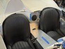
I tend to overly obsess over some design aspects far more than others, and for whatever reason, the rear center area between the two seats was something that took a long time for me to get reasonably correct. From my research, it seems that the design varied for different D Types, though I couldn’t nail down a rhyme or reason other than it being dictated by the varying shape of the transmission cover, which also didn’t seem to have a rhyme or reason (probably transmission choice related, but who knows). The one thing that did seem consistent was the mystery hole between the seats.
View attachment 152126
Through the kindness of a stranger on the internet who owns an actual D Type, I was able to obtain a measurement for the ‘mystery hole’, and from that ‘Rosetta stone’ I could roughly figure out reasonably proper proportions for everything else. I chose a design that worked well with the overly large size of the RCR center tunnel and got to it.
View attachment 152119
Only modification I made to the monocoque tub was to cut out a small section like Chuck did with his build.
My current fabrication skills and limited tools prevented me from doing an elegant one piece design like Chuck did, so I opted for a lot of pieces and drilling a lot of holes.
View attachment 152120
View attachment 152121
Side pieces built. Slightly off-kilter to accommodate the off-kilter cockpit design.
View attachment 152122View attachment 152123View attachment 152124View attachment 152125
Center section is now done aside from cleaning, adding rivets, and eventual painting. Since I’m using bucket seats and not the traditional D Type style ‘seat squabs’, I’ll probably add some curved aluminum trim pieces behind the seats to try and make it look a little less weird.
View attachment 152128