GT40 Build - GT Forte' space frame - Question about front suspension

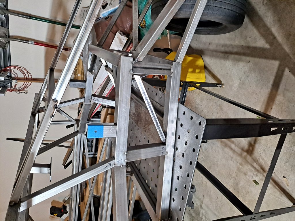
Hello. I've just started poking around this forum and, I'm a noob when it comes to building kit cars (please be gentle). I've purchased and took delivery of a GT40 chassis flat pack from GT Forte'. Minus the roll hoop and missing horse shoe assembly, the frame is nice and tacked up (I can fabricate whatever is missing). I would like to focus on getting the frame to roll right now.

I've never worked on anything other than stock suspension componentry. Building out suspension from scratch will be completely new and I hope I'm headed in the right direction.

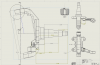
GT Forte' assembly instructions does not discuss the front suspension geometry. So, I've decided to purchase a cheap set of front Mustang MII spindles and upper/lower Moog ball joints to begin determining the desired front-end suspension geometry. NOTE: I do not intend on using these components in the end-build, I am using them to learn right now.


"And now I bare my chest for the Archers bolt(s)"


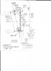
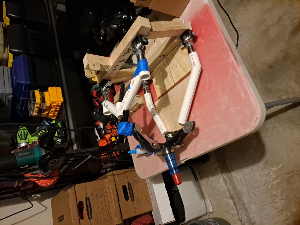
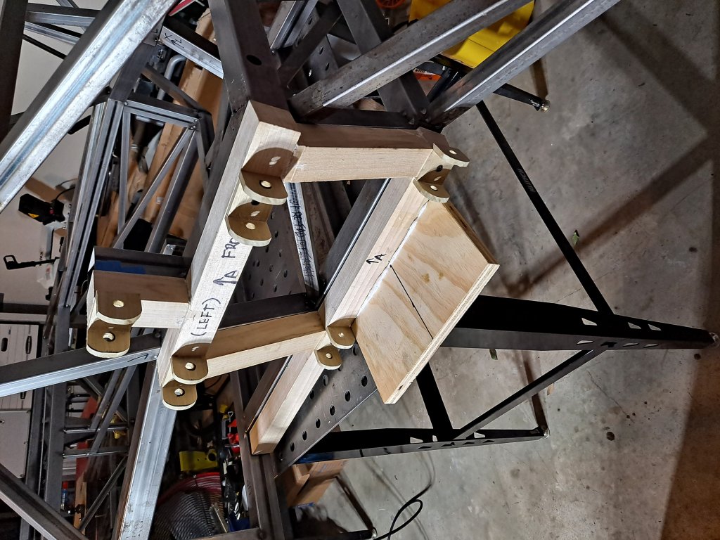
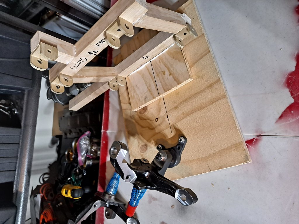
I've decided to fabricate a wooden replica of a portion of the GT40 space frame left front chassis to work from...


... and attach the Mustang spindle to a base in order to articulate the two pieces. This allows me to work inside at 2AM without p!ssi!ng off my GF.


From what I have read some GT40 builders are going with 15 X 8 wheels for the front and 15 x 10 wheels for the rear of their cars. I am considering doing the same.

With that in mind (and assuming 15 inchers are the way to go) my next task is to determine where the 15 x 8's sit in orientation to the chassis. This will allow be to determine what will be needed as far as upper and lower a-frames are concerned (working out the geometry in particular). Of course the upper and lower a-frames must be the same distance/length from the chassis in order to allow for fluid up/down movement.

At this point "I believe" I need to choose a wheel size (height/width) for the front, grab the specifications for this wheel, and then measure back to the chassis and work out the geometry while taking into consideration the turn angle of the wheel allowing for fender/chassis clearance. I am planning on constructing the a-frames using adjustable (at least three inches) linkages.

So, am I totally high taking this approach? Is there a better method of doing this? Is there life on Mars?

I want to learn and have fun at the same time.

Many thanks Guys/Gals!


PS: Sorry about these gallery images. I could not find a way to rotate them +90
 

Doc Watson

Lifetime Supporter
Phew, where to start.....

Bump steer, Ackerman, camber, toe and castor.......

Ok first off, welcome to the build forum and I am already envious of your workshop space.

There are many things to consider when designing the front suspension and I have listed some of them above, if you can finalise the wooden mock up by attaching the spindle using upper and lower wishbones then you can simulated the movement of the wheel both up and down and also (if you add the steering rack) you will be able to check bump steer.

No archers bolt, a crossbowman's bolt or an archers arrow......

If you are unfamiliar with any of the terms above google them and then we can talk reverse Ackerman later (joking).

A good start and look forward to seeing more progress. Do you have a body? engine? gbox?

Andy
 
LOL Andy. "No archers bolt, a crossbowman's bolt or an archers arrow" is totally correct.

I have not selected the body yet. Was going to go completely with GT Forte' ... but cannot get an email response lately. Southern GT (I live in Texas)?

YesSir...the wishbones are the magic. I am wanting to determine what it is need to flesh the upper an lower out.

Since this car will be so light, I am thinking about a 351 (302 at the least) plus Audio tranny.

I do not do cars for a living. Cars are more of a hobby (I write software) and I find myself helping folks a lot with their machines.

Many thanks for your time.
 

Doc Watson

Lifetime Supporter
Well I teach software so most of my time is spent fixing peoples computers...... If you have ever done any 3d programming then you could write some software to simulate the geometry although the physical mock up your making will probably be the better route. Also see if you can get other GT Forte owners to discuss what they did.
 

Charlie M

Supporter
You may want to consider picking up the body next. The approach I took was to position the wheels and tires then design inward. I did this to make sure I had them positioned properly to fit under the body. I made a full size wooden mock-up of the first iteration of the chassis design. You have your chassis tacked together already so you don't have to do that.

That first iteration of the chassis was made to use C4 Corvette front uprights and control arms. The full size model helped me discover that the control arms were too long and they didn't leave a lot of room in between for my feet.
 

Attachments

  • GT40 Body1b.jpg
    GT40 Body1b.jpg
    290.4 KB · Views: 407

Mike Pass

Supporter
The GTForte chassis was set up to use Ford Granada Mk2 uprights and a Ford Cortina Mk3-5 steering rack. As you are using Ford Mustang spindles this will mean a change in geometry.
I would suggest you do an initial trial with CAD - cardboard aided design!
From your built chassis you have the location of the front suspension wishbone pickup points as seen from the front (see pic)
Start by placing them initially on the top and bottom chassis rails (may need to move them later).
Put the top and bottom joints on the Mustang uprights and carefully measure from the centre of the top swivel joint to the centre of the lower ball joint. This is the effective height of the upright.
As a starting point use these measurements
Body width at centre of front wheels 71.5"
Wheel arch lip 0.5"
Front track with 215/60x15 tyres measured from outside of tyres 68"
Front track from outer bottom edges of wheels 66.5"
Chassis to ground 4"
Your chassis width at the top and bottom

If you can borrow a wheel and tyre fit your uprights and brake discs etc. and measure from the wheel outer to the top and bottom ball joint centres. Or calculate from the offset measurements of the wheels, brake disks etc. you are going to use. Note that the actual lengths of the wishbones is the distance from the centre of the pivots and not the actual metal of the wishbones.
From this info you can create a 2D model of your front suspension( as seen from the front). (see diagram)I would use use thin plywood for the chassis and, links and upright etc. and small bolts and washers where the pivots are. This cardboard suspension can then be moved up and down and the roll centre found at different positions. It is easy to move the inner pickup points and wishbone length to see the effect it has on the roll centre. This is very quick and easy with thin ply as the new points can be drilled and moved. The idea is to find the pickup points where the roll centre remains in the same place as the suspension moves ( as far as possible) This makes the car stable feeling and much nicer to drive.
Once this is done then the issue of bump steer can be addressed.
Because the ends of the wishbones and the end of the steering track rod move in arcs then the ends move in and out relative to the chassis.If the track rod end moves a different amount compared to the upright then the steering will be turned as the suspension moves and the car will be steered - this is bump steer and is very nasty as the the car will dart about as it hits bumps and dips.
It is impossible to remove all trace of bump steer but it can be reduced so it has no real effect.
There are different ways of reducing bumpsteer
Set the inner end of the track rods in the same plane as the four inner wishbone pickup points. The inner ends of the track rods are set by the length of the steering rack so the length of the rack is important. There are companies who will do racks of custom length. The standard Cortina steering rack is slightly too long but it will work.
Move the rack up and down and back and forth until the bumpster is eliminated in the normal range of suspension movement 2" up and 1" down.
To check for bump steer buy a cheap laser pointer from Ebay and attach it to the face of the hub so it shines on a wall or big sheet of board. Use a jack to move the suspension up and down a small increment at a time and mark the laser spot position. If there is no bump steer the plot will be a line which is as close to vertical as possible. If it is at an angle this indicates that the upright is turning as the suspension goes up and down. Try different positions until the best rack position is found.

Hope this helps
Cheers
Mike
 

Attachments

  • Roll centre 2.jpg
    Roll centre 2.jpg
    61.2 KB · Views: 410
  • Bump steer.png
    Bump steer.png
    166.6 KB · Views: 490
Last edited:
"The idea is to find the pickup points where the roll centre remains in the same place as the suspension moves ( as far as possible) This makes the car stable feeling and much nicer to drive. "

I have to modify this slightly:

It is not necessarily the stability of the roll center height. A very high roll center will make a very unstable straight line situation because the tire patch moves laterally with wheel travel. The ideal for stability for that is to maintain the roll center at ground level. A compromise (in terms of a higher roll center) is usually done to reduce roll, Since the roll center does tend to move vertically with wheel travel, an above-the-ground static roll center will tend to be more "grounded" as the suspension compresses on roll.
 

Mike Pass

Supporter
A bit more info.
The sketch should help you to work out some starting points for your wishbone arm lengths. The measurements of tyre diameter and the distance of the brake disk outer face to the wheel rim are taken from my GTD but should give a reasonable starting point using the distance from rim to rim from previous post. The other pic. is a drawing of Mustang 2 upright.
Suspension layout
The basic idea is that the camber increases as the suspension moves upward (bump)and decreases as it moves downward (droop). This is to keep the tyre flat to the road as the car rolls when cornering. The trick is to match the camber change to the angle of roll of the car. As the car rolls the outside wheel will get more camber and the inside wheel to get less camber and so keep both tyres flat to the road.
The usual set up is to have the top wishbone shorter than the lower wishbone and for the lower wishbone to be horizontal or slightly angled down. The upper wishbone is angled upwards at a greater angle. When the suspension moves up the top wishbone pivot moves inwards quite a lot as the upper wishbone is relatively short. The lower wishbone pivot moves outward or inward very slightly. So the upper pivot moves inwards much more than the lower and therefore the camber increases as the suspension moves upwards. The opposite happens as the suspension moves down. The greater the difference between upper and lower wishbones the greater the amount of camber change as the suspension rises and falls.
So the loaded outer wheel in cornering gets more camber and the inner wheel gets less camber. This camber change should cancel out the roll of the car and keep the tyres flat to the ground. The car roll rate should be compensated for by the camber changes of the wheels. The amount of car roll is determined by the spring rate, the antiroll (sway) bar stiffness and the roll moment (the distance between the roll centre and the centre of gravity) and the mass of the car.

The king pin inclination (KPI) is the angle between a line drawn through the top and bottom joints of the upright and the vertical. This is 11 degrees in the case of the Mustang 2 uprights. The KPI is a fixed angle as part of the upright design. Ideally the line through the top and bottom swivel (king pin axis) should pass through the centre of the tyre but this is often not possible. The KPI has a significant effect on the car’s turn in to corners as it determines the rate of camber change as the upright is turned and slightly alters the wheel height.

On a GT40 set the static camber to about 0.5 degrees negative (top of wheel tilted in) as a starting point.

Castor is the angle of the king pin axis as seen from the side. The line extended should meet the ground ahead of the wheel. The bottom swivel will be ahead of the upper swivel joint. This castor effect is what provides the self-centering effect of the steering. More castor makes the steering wheel heavier to turn. As a starting point set the castor to about 4 degrees for a non-powered rack.

For Mustang 2 front suspension rotor, brakes etc, Speedway Motors do 4 bolt 4.5” pcd and 5 bolt 4.5” pcd and 4.75” pcd in a range of sizes with various brakes up to Willwood 4 pot. Check which will fit inside the diameter of wheel you want to use. Hopefully the 11” will be OK.

Toe in. Very little toe in. Start with about 0.5 degrees in.

Cheers
Mike
 

Attachments

  • Suspension drawing.jpg
    Suspension drawing.jpg
    111.4 KB · Views: 522
  • Screen Shot 2021-05-11 at 17.47.28.png
    Screen Shot 2021-05-11 at 17.47.28.png
    620.3 KB · Views: 424
Many thanks Mike. I certainly appreciate the time you have spent on your write-up (it has not been in vain). The past few days I have take a few measurements from my Mustang II kingpins and roughed out a my PVCAD model (Poly Vinyl Chloride Aided Design just to get a vague notion of what the upper and lower wishbones would look like. I know this is not the final geometry, but it helps to visualize where this is going.

Right now I have been sending email to Tornado Sports Cars in order to get a quote on the cost for making and shipping a MKII shell to the USA. I have not heard back as of yet. I was planning on taking your "build from the outside in" approach (going to need a shell anyway at some point).

Thanks again,
Don
 
Back
Top