GTD 40 Transaxle upgrade R21 Renault to Porsche G50

Howard Jones

Supporter
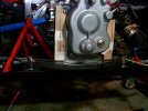
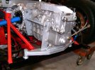
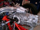
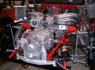
So it fits! !!!!!!!!!!!!!!!!!!!!!!!!!!!!!!!!!!!!!!!!!!!!!!!!!!!!! Yea !!!!!!!!!!!!!! I'll sleep tonight! !!!!!!!!!!!!!!!!!!!!!!!! yea!

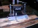
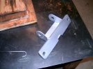
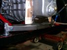
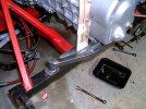
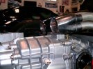
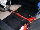
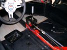
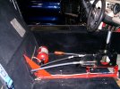
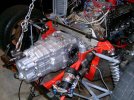
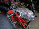
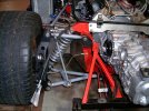
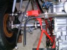
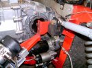
I think that it has good clearance generally so I dont believe I will be making any big changes to the chassis. I stiil can lower the engine about a inch so that only helps pretty much everywhere. I am going to do that first with new homemade engine mounts. The starter was what I was worried about but I think I only need to notch the big vertical chassis menber a little bit if at all.

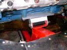
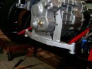
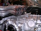
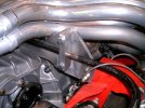
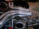
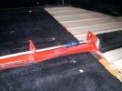
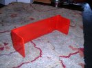
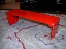
You can see that the aluimium chassis crossbrace/rollbar mount is un-altered. This means that most of all the headers will fit all the way back to the collectors. The rest is pretty easy to remake as necessary.

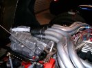
Two things that are not optimal: vertical driveshaft angle and clearance about the muffler. The driveshaft angle will improve with the lower engine and the muffler is too loud anyway. Theres a new one in the future.

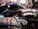
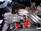
Next installment after I have the engine mounts made and the engine in final situ.
 

Attachments

  • HPIM2684.JPG
    HPIM2684.JPG
    379.8 KB · Views: 221
  • HPIM2685.JPG
    HPIM2685.JPG
    422.6 KB · Views: 198
  • HPIM2686.JPG
    HPIM2686.JPG
    395.2 KB · Views: 175
  • HPIM2687.JPG
    HPIM2687.JPG
    426.1 KB · Views: 168
  • HPIM2688.JPG
    HPIM2688.JPG
    404.4 KB · Views: 164
Last edited:

Howard Jones

Supporter
I have finally got the engine mounts done. The rubber engine mounts that were on the car created quite a bit of thinking. I was hoping to simply make a jig using one of them and then duplicate in steel while incorporating lowering the engne a inch. The rubber makes the jig dimentionally unreliable so it took a while more or less using the whole engine as a jig and contant measure, measure, measue to get it right. I ended up with the engine on centerline within a 1/8 inch and level as well as a inch lower than before.

The first picture is the jig behind one of the finished mounts. On to the rear GRBX mount. Then I'm going to see where I am with the Axles/ CV joints. Its gonna be close........ So far no chassis modifications.
 

Attachments

  • HPIM2690.JPG
    HPIM2690.JPG
    356.1 KB · Views: 135
  • HPIM2691.JPG
    HPIM2691.JPG
    383.5 KB · Views: 141
  • HPIM2692.JPG
    HPIM2692.JPG
    370.2 KB · Views: 146

Howard Jones

Supporter
Some more progress. This bracket will dupilcate the orginal Renault mounting system. The time consuming part is all the hand cutting and fitting the steel pieces before welding, You would be suprised just how precise things need to be, and that is a challenge to my old eyes. I use the cut it out in cardboard first method. You can see how its done by a caveman here. No dang 3D printin in these parts!!!!!!!

The good thing is doing it like this leaves me with a lot of time to think it through, and that a good thing.

Oh I've figured out a way to mid mount from the adapter plate, More on that later.
 

Attachments

  • HPIM2693.JPG
    HPIM2693.JPG
    274.9 KB · Views: 112
  • HPIM2694.JPG
    HPIM2694.JPG
    257.7 KB · Views: 110
  • HPIM2695.JPG
    HPIM2695.JPG
    379.9 KB · Views: 128

Howard Jones

Supporter
The rear lower GRBX mount is complete. It mounts in the same mount points that the R21 did, As you can see it is made in three pieces so as to make maintance easier. It is much easier to remove the three pieces indvidually than to try and wrangle the whole contraption out of there. It was also a lot easier to make them one at a time once the preceeding piece was in place. This greatly reduced error stacking. I also began to reinstall the shifter system.

So now I need to put the rear body back on and see where the clearances are.
 

Attachments

  • HPIM2696.JPG
    HPIM2696.JPG
    268.6 KB · Views: 97
  • HPIM2697.JPG
    HPIM2697.JPG
    294.6 KB · Views: 78
  • HPIM2698.JPG
    HPIM2698.JPG
    333.9 KB · Views: 91
  • HPIM2699.JPG
    HPIM2699.JPG
    284 KB · Views: 110

Malcolm

Supporter
Hi Howard

Just looking up close in your pictures, it seems you have rubber engine mounts but this gearbox mount appears to be solid steel to chassis mounted. Are there any rubber bushes on the gearbox? Rubber something in those vertical tubes? Might crack the casing if not? Hope my eyes are deceiving me!!!!!
 

Howard Jones

Supporter
The engine mounts are solid as well. The black tubes you see between the chassis vertical tabs is to prevent them from being squeesed together when the thru bolt is tightened and maintain the clamping force.

I might add that this engine was ballanced down to 1 gram. IMHO ballanced engines do fine with solid mounts. When this gearbox was in my SLC it had similar mounting brackets and solid engine mounts. No problem there either.

Thanks for the interest, its really nice of ya all to alert others when you see something.
 

Howard Jones

Supporter
Next problem.

Ya al knew I was going to have to start cutting things up a bit right? The headers come very close to being OK. BUt not quite. When they were made for the orginal GTD/Renault R21 install they were angled downward at the end of the primary tubes so as to utilise the standard Renault configuration. Input shaft above the ring gear centerline and output shafts. This araingemnt places the main mass of the gearbox low in the chassis and leaves more room above the gearbox.

Flipping the gearbox as I did with the G50 raises the main mass of the gearbox but allows for lowering the engine mass becasue the input shaft is now below the centerline of the ring gear and the outputs shafts, Better I think, but it does eat up some of the room above the gearbox under the rear bodywork, The good news is there is a lot of room under the bodywork still so thats not going tp be a groblem but it does create some interfernce issues with the rear portion of the exaust system as it was orginally designed.

So its sawsall time! Ya, ya al knew that was coming. Admit it.

I had some left over collectors on the shelf so I cut them up as bit, as well as the last couple of inches of the primary tubes and got this far, (second set of pictures). This set of collectoes are pretty cheap but I used them as sort of a prototype exercise to see what I need to do. The other thing complicating the header fitting is that they were made using a sand forming method, They look cool all nice and flowing but it makes it them hard to modifiy because there is very little straight tubing anywhere to use as a datum. It will work out in the end but a more conventional built set of headers would have had nice straight ends on the primarys. This would have made things a lot less difficult.

Here's the good news. The orginal collectors, last picture, that came on the GTD orginal set of headers are quite a bit more compact. The next victim of the sawsall!!!!!! Watch this space.

More Horror to come! Chop! chop! chop!
 

Attachments

  • HPIM2700.JPG
    HPIM2700.JPG
    366.6 KB · Views: 48
  • HPIM2701.JPG
    HPIM2701.JPG
    387 KB · Views: 47
  • HPIM2702.JPG
    HPIM2702.JPG
    369.1 KB · Views: 48
  • HPIM2703.JPG
    HPIM2703.JPG
    313.8 KB · Views: 45
  • HPIM2704.JPG
    HPIM2704.JPG
    326.7 KB · Views: 45
  • HPIM2705.JPG
    HPIM2705.JPG
    339.2 KB · Views: 51
Last edited:

Howard Jones

Supporter
Heres the next installement to the saga,

I did what I said I would never do again. Reuse a set of headers to make a set of headers. To be fair to myself I really didnt need to make a new set of headers but after about a hundred cut, trim, remeasure, cut trim, remeaaure.........etc I feel like I did. As i mentioned before these headers are a sand formed set, they look cool but there are no straight segments and that makes it very difficult to move the collectors one way or another. I found through trial and error that the collectors needed to move forward, shorter primarys, about 3 inches to get me clearance over the gearbox fat spot. And the short pipe section of the collectors need to angle upward as well as be made from 2 1/2 pipe instead of 3 inch.

One of the problems was the headers were ceramic coated inside and out as well a being used and haveing carbon inside. I cannot weld old dirty pipes. I know it can be done, But I cant. I got them as clean as I could but I'm just a old hotrod self taught hack. So it was a very difficult weld job. In the end they came out so that they fit but I.m really not happy with them and I may have some made now that I have an example.

I also finished the main chassis cross brace and the rollbar mounts. Binned the rubber bar clamps and made a pair out of aluimum. I got to use my mill so that was fun.

I now have a exhaust system to work with that will fit under the bodywork and clear all the powertrain pieces, The rest is just either finding a muffler that fits the envelope or making one and then get the tail pipes out of the rear of the car. Here is an example of my thinking below. They will make custom designs like this basic kind for not too much money. I think I will talk to them as I progress.


Check them out Spintech mufflers.


The next big issue is going to get clearance around the driveshafts where they exit the chassis going towards the uprights on the inboard side. For sure new driveshafts as well as stubshafts.

We talked about stubshafts on GTDs before, and I believe that the two sizes are the VW vans size CV's and the 930 size CV's. I will need to use the 930 type. Question for my English buddies. Are they the same dimentionaly other than the CV adaptation of the drive plates?. Mainly, will the 930 type simply fit through the bearings and be the same lenght, splines, etc. as the smaller size type?

Thanks in advance.

Here's the evidence.......
 

Attachments

  • HPIM2706.JPG
    HPIM2706.JPG
    372 KB · Views: 14
  • HPIM2707.JPG
    HPIM2707.JPG
    429.4 KB · Views: 15
  • HPIM2708.JPG
    HPIM2708.JPG
    367.2 KB · Views: 15
  • HPIM2709.JPG
    HPIM2709.JPG
    324.4 KB · Views: 16
Last edited:
Back
Top