
You are using an out of date browser. It may not display this or other websites correctly.
You should upgrade or use an alternative browser.
You should upgrade or use an alternative browser.
Hacking an IDA 'Weber', turning it into EFI
- Thread starter Jazz
- Start date
One must also pay attention to the injection angle of the injector.
These are not only straight but also with predefined angles.
At Bosch, for example, the range is -10° / -5° / 0° / +5° / +10°.
(As far as I know)
Here is an example how I designed this for an Audi V10 engine.
The injectors need +10° here, so that you can still mount them.

These are not only straight but also with predefined angles.
At Bosch, for example, the range is -10° / -5° / 0° / +5° / +10°.
(As far as I know)
Here is an example how I designed this for an Audi V10 engine.
The injectors need +10° here, so that you can still mount them.
Yes I noticed that when I was looking at what injector I wanted to use.
Because of the packing constraints, I'm going with 'Pico' sized injectors, and there are not that many spray angles available.
I also might have to use 'extended nose' configuration due to the thickness of the casting of the manifold. That only comes in 'straight shooting' configuration in 2 spray cone angles. I'll probably have to draw a sketch to figure out what angle would work for me.
"....I'll probably have to draw a sketch to figure out what angle would work for me."
This is certainly a very good idea!
By the way, there are also retrofit systems for weber carbs. Here only the throttle valve is used - everything else flies out. The injector sits in the middle, where normally the mixing tube sits.
That would be very easy to retrofit.
I have installed it on an Alfa, it works very well
That's a nifty system! Looks a lot like the early F1 car fuel injection system, where they also had injectors suspended over ITB's. Saw a few of those configurations at the Ferrari Museum in Modena Italy.
I don't think I'd like free-spraying fuel in the back of my GT though, without a manifold around it like you'd have on your Alfa.
Maybe one day for a fire breathing drag strip beast? Would be awesome to see your fuel being delivered as you hurling down the strip!
I don't think I'd like free-spraying fuel in the back of my GT though, without a manifold around it like you'd have on your Alfa.
Maybe one day for a fire breathing drag strip beast? Would be awesome to see your fuel being delivered as you hurling down the strip!
Pico njectores come in single hole (480cc) and twelve hole (the larger ones) and they beheave different.
Was spraying on top of my butterfly with the single hole first, swapped to the larger 12 hole and ran into running issues so ended up going back to tye single holes.
You could see tye difference clearly in spray pattern.
Was spraying on top of my butterfly with the single hole first, swapped to the larger 12 hole and ran into running issues so ended up going back to tye single holes.
You could see tye difference clearly in spray pattern.
That's a nifty system! Looks a lot like the early F1 car fuel injection system, where they also had injectors suspended over ITB's. Saw a few of those configurations at the Ferrari Museum in Modena Italy.
I don't think I'd like free-spraying fuel in the back of my GT though, without a manifold around it like you'd have on your Alfa.
Maybe one day for a fire breathing drag strip beast? Would be awesome to see your fuel being delivered as you hurling down the strip!
One of the reasons for an anti-reversion shield being placed over the top of Webers in the GT is to trap the reversion fuel spray and allowing it to become liquid once again where it then drips down to the top of the plenum and evaporates...
This helps to keep the back end of the car from becoming a bomb... it will also prolong the life of the rear windscreen.
JP, which 480cc Pico's are you using?Pico njectores come in single hole (480cc) and twelve hole (the larger ones) and they beheave different
I'm currently looking at the BOSCH EV14 series, not sure yet if I need the 'extended nose' version or not. Was going to use the cone spray pattern as well, thats how i'm aiming the injector in any case. The idea is to inject below the throttle plates, should give better fueling during idle and low load conditions I hope.
Where are you based JP, its good fun to get to know fellow Dutch GT owners, not that many around I think. I met Geert-Jan a few days ago with his car where he was getting a new exhaust fitted.
Weber Pico IPW 069. Pic shows a 510cc.
I live in Leerdam between Den Bosch & Utrecht.
I know Geert Jan very well.
I am still building my KVA "B" type. A long & slow process.
OK, update:
Manifold is at the machinist to drill a few holes. Pray he does it right. 0.1mm tolerance fit, to allow for gluing the injector bungs in place with Loctite 638. (suitable to 200degC, with 70% of strength left at 150degC, should work).
Also found a guy that makes shaft sealing kits for the inside of the IDA webers. This is a known air leak point, and can generate erratic idles, difficult to balance webers etc. Thought it was worth a shot for 15dollar, and supporting someone in the community.


Also fabbed all the fuel lines, that connect the fuel 'banjo' to the AN fitting T-pieces, by using the float/fuel bowl space.
Good fit, happy with this.


Want to make a reliable throttle pedal position sensor, as TPS's are used for a crucial part of the tuning of ITB's in modern day ECU's.
So, sensor is key, but more importantly is a good reliable connection between the throttle shaft and the sensor.
Commercially available kits are not working for me, as they apear sloppy and prone to significant hysteresis.
Was drawing up an aluminium adapter, transferring the M7x1.0 thread on the throttle shaft, to a 8mm round bar for the 'D-type' 8mm orifice in the typical TPS sensors.. Not a massive big deal, but found that there are more nut-jobs like myself in the world.
Emerald ECU manufacturer actually makes these adapters, and sells them for 2.5 pounds each. HOW?
Love those kind of finds.. Ordered a bunch of those, so I can mess up my filing and still get a tight fit in the TPS!

Manifold is at the machinist to drill a few holes. Pray he does it right. 0.1mm tolerance fit, to allow for gluing the injector bungs in place with Loctite 638. (suitable to 200degC, with 70% of strength left at 150degC, should work).
Also found a guy that makes shaft sealing kits for the inside of the IDA webers. This is a known air leak point, and can generate erratic idles, difficult to balance webers etc. Thought it was worth a shot for 15dollar, and supporting someone in the community.
Also fabbed all the fuel lines, that connect the fuel 'banjo' to the AN fitting T-pieces, by using the float/fuel bowl space.
Good fit, happy with this.
Want to make a reliable throttle pedal position sensor, as TPS's are used for a crucial part of the tuning of ITB's in modern day ECU's.
So, sensor is key, but more importantly is a good reliable connection between the throttle shaft and the sensor.
Commercially available kits are not working for me, as they apear sloppy and prone to significant hysteresis.
Was drawing up an aluminium adapter, transferring the M7x1.0 thread on the throttle shaft, to a 8mm round bar for the 'D-type' 8mm orifice in the typical TPS sensors.. Not a massive big deal, but found that there are more nut-jobs like myself in the world.
Emerald ECU manufacturer actually makes these adapters, and sells them for 2.5 pounds each. HOW?
Love those kind of finds.. Ordered a bunch of those, so I can mess up my filing and still get a tight fit in the TPS!
I'm intrigued by the behavior of the fuel injection here, at times the fuel is even coming back into plenum chamber.
May be excess back pressure in the exhaust as the turbo slows down when the throttle snaps shut. This slowing the exhaust turbine which then leads to the pressure building in the chamber due to exhaust valve overlap with the intake valve. ie both valves are open for a short period of time. Exhaust Air then flows back into the plenum. I don't know, i am not an expert.
There is another video on the web somewhere that shows some of the older F1 engines running. you can clearly see what they call "Fuel Stand Off" under certain conditions. A cloud of fuel vapor appears above the trumpets. I think its a video of a Renault F1 engine. maybe the V10 on the dyno that i am thinking off. I will see if i can find it.
As for the rest of the fluid you see running down the floor of the plenum. I'm guessing that is blow by from the crank case that is coming from the PCV valve back into the intake plenum to be re-burnt.
Ryan
Updates coming in fast and hot.. Got the intake back from the machine shop today. They did an awesome job in aligning and tolerance fit. 0.05mm which is nice and snug.


With the 'carbs' installed, I think I can conclude that it will actually work.. but is going to be a very tight bunch of plumbing!
Any tips on bending aluminium tubing in tight radii? Heat, no heat? i'm using a nylon 4mm rod to 'fill' the ID when bending, to prevent kinking the tubing.

With the 'carbs' installed, I think I can conclude that it will actually work.. but is going to be a very tight bunch of plumbing!
Any tips on bending aluminium tubing in tight radii? Heat, no heat? i'm using a nylon 4mm rod to 'fill' the ID when bending, to prevent kinking the tubing.
Ian Anderson
Lifetime Supporter
That looks really good.
i have a question though ...will all that interfere with the throttle opening mechanism?
ian
i have a question though ...will all that interfere with the throttle opening mechanism?
ian
That's the next challenge Ian. I believe it can be done, as the plumbing for the injectors goes to the black AN fittings coming out of the weber body, and should therefore not cross the area where the throttle linkage system is mounted.
The throttle cable might have to connect on the side, and i'll have to think about that a little more once the center plumbing is sorted out.
We're eating this elephant in small bites.
The throttle cable might have to connect on the side, and i'll have to think about that a little more once the center plumbing is sorted out.
We're eating this elephant in small bites.
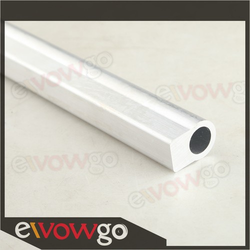
Dash 8 Fuel Rail Raw Extrusion -8AN Aluminum Length:330mm (1.08 Feet) | eBay
Find many great new & used options and get the best deals for Dash 8 Fuel Rail Raw Extrusion -8AN Aluminum Length:330mm (1.08 Feet) at the best online prices at eBay! Free shipping for many products!
www.ebay.com
something like that.
Would be easier to hide....you might be able to do one extruded fuel rail section per carb, and then just have one connection back onto the AN fitting coming out of the carb base.
Similar threads
- Replies
- 3
- Views
- 1K
- Replies
- 24
- Views
- 6K
- Replies
- 18
- Views
- 4K
- Replies
- 3
- Views
- 2K
- Replies
- 13
- Views
- 3K