
You are using an out of date browser. It may not display this or other websites correctly.
You should upgrade or use an alternative browser.
You should upgrade or use an alternative browser.
Homemade CFRP mid engine sports car
- Thread starter Paul Bristo
- Start date

Hi Michel, glad you like it !
thanks for the heads up, I got a recess in there for the screen, in the image below the screen bonds to the hashed line area, and the area circled there is a 9mm recess so the screen is flush with the roof.
I decided to design it so that there is no visible A-pillar structure (the screen sits over it), I regret this now as I worry if the door is not stiff enough it could strike the edge of the screen when closing .. but its too late to change now. I will need to make sure there is a healthy clearance and also the door is nice and stiff.
Ok, new year and time for a new update. While I wait for the warmer weather to mould the main tub I have been working on some of the smaller panels that I can move indoors to cure. The part in the picture is the RH sill inner (it will join to the main tub to close the sill section).
I had some success with using an IR heater to post cure the parts, hanging it from the roof I can raise and lower it to get the desired temperatures. I can get up to 90degC on the part and so solves a big headache of how i'm going to post cure these parts.
Also been busy making 3D printed cores to hold the suspension attachment inserts for when i make the main tub. The printed frames hold pre-tapped aluminium blocks in the right place so I have the desired suspension geometry. The holes are filled with plastercine to prevent the resin filling them up (can be scraped out after). The 3D printed parts will be surrounded by foam core, and sit between the layers of carbon fibre.


I expect i'll have a few more months of down time so i'm considering making one of these 'mpcnc' DIY CNC routers;
. I already have a 3D printer and a spare router and the ability to mill up some simple aluminium brackets etc is bound to be incredibly useful later in the project so i see it as worth a shot. But this is some way out of my comfort zone, would love to hear from anyone with previous experience with milling aluminium.
I had some success with using an IR heater to post cure the parts, hanging it from the roof I can raise and lower it to get the desired temperatures. I can get up to 90degC on the part and so solves a big headache of how i'm going to post cure these parts.
Also been busy making 3D printed cores to hold the suspension attachment inserts for when i make the main tub. The printed frames hold pre-tapped aluminium blocks in the right place so I have the desired suspension geometry. The holes are filled with plastercine to prevent the resin filling them up (can be scraped out after). The 3D printed parts will be surrounded by foam core, and sit between the layers of carbon fibre.
I expect i'll have a few more months of down time so i'm considering making one of these 'mpcnc' DIY CNC routers;
Bryan Koehler
Supporter
Thats looking good paul!!! What cad software do you use? Solid works? Fusion360? Inventor? Ive been learning fusion 360 but im still a novice at it. Also very interesting RTM process. Do you have any videos of tje process of loading the mould with cf and setting up the tubing, peel ply, bleeder cloth etc... would like to see how one goes about getting the resin to flow properly thru the mould.
Yes I use fusion for most cad work, its a really powerful tool considering its free for hobby use. For the composites process work I strongly suggest to watch the videos on Youtube by 'easy composites', they are really well put together and show everything step by step, I buy a lot of my material and equipment from them and really can't fault them.
slowly starting to assemble the tool for the tub. re-checking and re-polishing each section in turn before bolting and sealing in place. Another week or so for this, then a leisurely 4 weeks or so of laying the plies into it, another week for the consumables layers and another for chasing air leaks .. am thinking should be ready to infuse by mid April.

I went ahead and built a CNC router from 3d printed parts, strapped a pen to it to test accuracy and squareness (and entertain the kids). So far so good. Next I plan to add a hose for compressed air blast and see if its able to mill small aluminium parts.

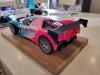
Last update .. i've been trying to find new ways to get the kids more involved. In doing so my son has told me that the car needs a big rear wing (i'm not convinced). So I gave him the job of designing it .. together we came up with 3 proposals which we printed and painted to try out on the scale model.
So here we have; no wing / wing 'A'(curved in 2 planes) / wing 'B' (curved in 1 plane) / wing 'C' straight wing. Thoughts ladies and gentlemen please ...


I went ahead and built a CNC router from 3d printed parts, strapped a pen to it to test accuracy and squareness (and entertain the kids). So far so good. Next I plan to add a hose for compressed air blast and see if its able to mill small aluminium parts.
Last update .. i've been trying to find new ways to get the kids more involved. In doing so my son has told me that the car needs a big rear wing (i'm not convinced). So I gave him the job of designing it .. together we came up with 3 proposals which we printed and painted to try out on the scale model.
So here we have; no wing / wing 'A'(curved in 2 planes) / wing 'B' (curved in 1 plane) / wing 'C' straight wing. Thoughts ladies and gentlemen please ...
Attachments
Tub update .. got all the plies laid up, peel ply and mesh layers on and bagged up .. now comes the great air leak hunt. Already a few hours in and still LOTS of leaks to sort.

23 kilos of epoxy resin later ..

Now need to patiently wait a week or more to fully cure before demoulding it, don't want to risk distorting the geometry.
After days of fruitless vacuum leak hunting I double bagged it, the second bag going all around the whole mould too in case that wasn't airtight. The double bag also let me keep the vacuum running while its curing so thats a bonus for the extra work.


June update;
Decided to coat the tub in a layer of UV resistant epoxy to protect it and to also rework some places with dry areas, so have been busy last few weeks sanding and polishing. Now need to find the suspension mount inserts and remove the plastercine, then attach the Sill inner panels, then rear inner panels, then fit the spider onto it.


I made and fitted the tunnel cooling pipes while its still relatively easy to flip the car over. The pipes are held in with high temp resistant epoxy composite brackets. I used 3d printed moulds to make these and this worked really well. I used glass fibre as hopefully less thermally conductive than carbon. Insulated the pipes.


Have not weighed it yet, i'll do this once all the extra panels are bonded on and the structure is complete, but my son has already tried to guess how heavy")

Decided to coat the tub in a layer of UV resistant epoxy to protect it and to also rework some places with dry areas, so have been busy last few weeks sanding and polishing. Now need to find the suspension mount inserts and remove the plastercine, then attach the Sill inner panels, then rear inner panels, then fit the spider onto it.
I made and fitted the tunnel cooling pipes while its still relatively easy to flip the car over. The pipes are held in with high temp resistant epoxy composite brackets. I used 3d printed moulds to make these and this worked really well. I used glass fibre as hopefully less thermally conductive than carbon. Insulated the pipes.
Have not weighed it yet, i'll do this once all the extra panels are bonded on and the structure is complete, but my son has already tried to guess how heavy
Hi Paul,
A CNC Router is a great addition to a shop. I built mine years ago for guitar making and just recently cut the aluminum pedal pads for my CLK-GTR build. View attachment 121696View attachment 121697
Thanks Vinny, I have had some success and some failures with the 3d printed CNC. Have been able to machine aluminium reasonably well, but I found if I try to cut for too long in one go two things happen .. The 3d printed parts start to soften from the heat and i lose stiffness, and second the neighbours complain about the noise


")
Made the sill inner panels, checking fit and alignment, hoping to get them bonded in next week


first test fit, starting to look a bit more like a car now !
got some more work to do on both upper and lower before i join them for good, maybe in a few weeks. Then .. window aperture, rear bulkhead, seats.

got some more work to do on both upper and lower before i join them for good, maybe in a few weeks. Then .. window aperture, rear bulkhead, seats.
finished building the sill inner areas. Still need to sand and polish some of the visible areas to get a flat and polished finish before i drop the spider on.


The spider is ready to be dropped onto the tub. I made the window aperture panel and have bonded it in. I will do the rear bulkhead panel once the spider is already fitted to the tub because it needs a good fit to the sills and floor. (yes it should fit through the door gap!). The upper bulkhead area will have removable panels, allow me access to harness attachments and for assembly.


made a bracket for the front damper mount, 1st real part made on the mpcnc router. Test fitted it with the rack as i knew it would be tight. There will be a second part on the front of the bracket to put the damper bolts into double shear.


The spider is ready to be dropped onto the tub. I made the window aperture panel and have bonded it in. I will do the rear bulkhead panel once the spider is already fitted to the tub because it needs a good fit to the sills and floor. (yes it should fit through the door gap!). The upper bulkhead area will have removable panels, allow me access to harness attachments and for assembly.
made a bracket for the front damper mount, 1st real part made on the mpcnc router. Test fitted it with the rack as i knew it would be tight. There will be a second part on the front of the bracket to put the damper bolts into double shear.
Congratulations !!!!!
For a home built project to achieve so perfect parts is really execptional
I know how this work can be hard after working so long and so many years onto LMP1 tubs but using modern and industrial tecnolgy as prepeg and autoclaves !!!!!!!
You are just doing a very very nice Jewel !!!!
For a home built project to achieve so perfect parts is really execptional
I know how this work can be hard after working so long and so many years onto LMP1 tubs but using modern and industrial tecnolgy as prepeg and autoclaves !!!!!!!
You are just doing a very very nice Jewel !!!!
fitted the roof on, like permanently now .. with glue and rivets and bolts and stuff

