How do i install fender vents

venius

Supporter
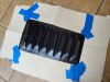
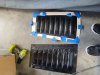
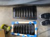
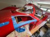
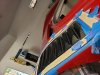
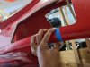
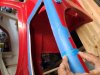
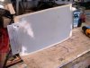
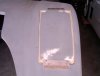
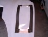
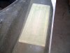
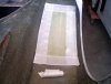
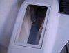
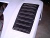
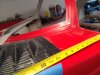
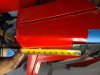
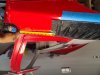
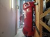
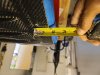
Im going to install my fender vents but wanted to make sure their in the right spot before I make my cuts. I was going to start the hole 9 1/2 inches from back edge of clam and 1 1/4 -1 1/2 inches "in" from the outside fender. I Moved the vents to fit snug on top. Just need to know if I'm In the same area as most slc owners with vents.... AND..I'm STILL debating after 2 days of thinking and looking at pics ...SHOULD I cut for vents or leave the fenders without vents.????... because once its cut...no turning back!! arrrgggghhhhh. "To cut or not to cut, that is the question "had me thinking for days!!! And still debating..arggghhh...sorry bout pics trying to figure out why they rotate
 

Attachments

  • 20230507_161203.jpg
    20230507_161203.jpg
    307.4 KB · Views: 210
  • 20230507_161551.jpg
    20230507_161551.jpg
    263.9 KB · Views: 214
  • 20230507_161609.jpg
    20230507_161609.jpg
    315.6 KB · Views: 180
  • 20230507_161702.jpg
    20230507_161702.jpg
    380.9 KB · Views: 177
  • 20230507_161930.jpg
    20230507_161930.jpg
    287.1 KB · Views: 162
  • 20230507_161756.jpg
    20230507_161756.jpg
    278.2 KB · Views: 156
  • 20230507_161744.jpg
    20230507_161744.jpg
    262.6 KB · Views: 180
Last edited:

venius

Supporter
Thanks!!! see Howard Jones post #301 . good info and where I saw his setup and got my answer.. I will put mine at 10 inches from rear of clam..
 
Last edited:

venius

Supporter
I made a template. there is A LEFT and RIGHT side vent. (Hard to tell with naked eye. See my template on vent) my vents are facing "inward" ....i Layed template down.Measured in 10 inches from The back clam ..thats my back cut.(markd INSIDE of template)...the template showed 3 inches "IN"(measured from the bottom and middle of fender) for "outside." side cut....(and DONT forget to " flip-over" the template,for the other vent!)
 

Attachments

  • 20230508_130256.jpg
    20230508_130256.jpg
    311.3 KB · Views: 118
  • 20230509_103407.jpg
    20230509_103407.jpg
    310.6 KB · Views: 109
  • 20230509_103505.jpg
    20230509_103505.jpg
    314.7 KB · Views: 108
  • 20230509_104135.jpg
    20230509_104135.jpg
    375.5 KB · Views: 112
  • 20230509_144104.jpg
    20230509_144104.jpg
    369.7 KB · Views: 107
  • 20230509_144054.jpg
    20230509_144054.jpg
    298.8 KB · Views: 109
Last edited:

venius

Supporter
I used a piece of tape...cut to 3 inches ...to check the "outside line" measurement. My left vent "outside" fender line will match the right side exactly...the back, of the outside line should line up with top of the fender ridge line...I'm going to "fine tune" the cutout using a block and hand sanding, add a "shelf" to "sit" the vents on , trim the vents, then fiberglass to make it nice ...as I saw on the other "SLC GODS" (see Howard Jones) builds and check the superlite build site also
 

Attachments

  • 20230509_104135.jpg
    20230509_104135.jpg
    375.5 KB · Views: 95
  • 20230510_100653.jpg
    20230510_100653.jpg
    264 KB · Views: 95
  • 20230510_100912.jpg
    20230510_100912.jpg
    268.1 KB · Views: 112
Last edited:

Howard Jones

Supporter
Like this:
Save the pieces of fender you cut out and repair them to leave a 1/8 gap all the way around when in the hole. The green stuff is mold release painted on masking tape because the resin will not stick to it. Now fix them in the holes and seal the gap on the outside with duct tape because the resin will not stick to duct tape. I screwed them on from the outside with sheet metal screws and then ground off the points inside. I filled the little holes after the fact with more fiberglass resin.

Now add fiberglass cloth in layers until it is about 3/32s thick and wide enough to form a shelf for the vent to sit on later. This additional fiberglass can be wider than necessary so you can form the shelf to suit. Now let it set up and pull the plug off......wala!

Add fastener plates as required

Here for both corners and side plates:

https://www.pegasusautoracing.com/p...61oMcY40BlkbvghQMhQNbRUyvQLsxTbhoCM04QAvD_BwE

Now you can take it out for repairs or replacement.

Note: Remember everything is handed L to R
 

Attachments

  • HPIM2065.jpg
    HPIM2065.jpg
    169.9 KB · Views: 113
  • HPIM2066.jpg
    HPIM2066.jpg
    144.3 KB · Views: 100
  • HPIM2067.jpg
    HPIM2067.jpg
    97 KB · Views: 107
  • HPIM2068.jpg
    HPIM2068.jpg
    101.3 KB · Views: 106
  • HPIM2070.jpg
    HPIM2070.jpg
    165.5 KB · Views: 94
  • HPIM2071.jpg
    HPIM2071.jpg
    198.1 KB · Views: 107
  • HPIM2073.jpg
    HPIM2073.jpg
    104 KB · Views: 121
  • HPIM2072.jpg
    HPIM2072.jpg
    123.8 KB · Views: 129
Last edited:
  • Like
Reactions: Vee
Here is how I did the one i am currently working on. I had seen them installed in various ways, but I went this route. There was enough material to just carve out a pocket. Took some time, but I am happy with the fitment. My plan is to use black machine screws to attach them.

1685455013919.png

1685455082324.png

1685455133433.png


One last fitment yesterday before the part go into final prime for paint.
1685455182814.png
 

Neil

Supporter
Here is how I did the one i am currently working on. I had seen them installed in various ways, but I went this route. There was enough material to just carve out a pocket. Took some time, but I am happy with the fitment. My plan is to use black machine screws to attach them.

View attachment 130133
View attachment 130134
View attachment 130135

One last fitment yesterday before the part go into final prime for paint.
View attachment 130136
There have been a number of posts about adding front fender vents to an existing body. I have been wondering about two things-

1. Why weren't the vents molded into the fenders in the first place?

2. The vents seem to be upside-down in some cases, disrupting the clean air flow. My understanding is that it is preferable that the vents are inverted rather that standing out.
Left Vents.jpg
 
I'd guess if one hasn't done extensive aero modeling that the "up" louvers would do a better job of pressure relief/extraction vs the smooth louvers that would need to be placed specifically at an area of know low pressure to do the best job. Many louvers on production performance cars I see now are not "inverted" but flush with the top of the fender while keeping more of the aggressive bladed look vs the smoother look in your image. Some are a sort of hybrid where the first few blades are up into the airstream and the following blades recede to a more flush configuration. I'm sure there's some arguments to be made about "venting" vs "extraction" of the pressure at the top of the wheel and the aerodynamic costs of each, but that's above my pay grade.
 
  • Like
Reactions: Vee

venius

Supporter
Here is how I did the one i am currently working on. I had seen them installed in various ways, but I went this route. There was enough material to just carve out a pocket. Took some time, but I am happy with the fitment. My plan is to use black machine screws to attach them.

View attachment 130133
View attachment 130134
View attachment 130135

One last fitment yesterday before the part go into final prime for paint.
View attachment 130136
Wow nice! I never thought of mounting them like that
 
Did you skin that carbon on the front clam or did you get carbon body parts? Looks great and will look even better when the rest is painted.
 
Thanks. They turned out decent I think. The pocket is basically the thickness of the carbon piece so they fit pretty flush with the outer surface.

1685549290793.png
 
Back
Top