
- Forums
- GT40 Replica Manufacturers' Corner
- RCR Forum - RCR40/SLC/917/Superlite Aero
- The SLC Clubhouse
You are using an out of date browser. It may not display this or other websites correctly.
You should upgrade or use an alternative browser.
You should upgrade or use an alternative browser.
Joel K
Supporter
This post covers pressure testing the cooling tubes. As Benjamin Franklin famously said “An ounce of prevention is worth a pound of cure”...

The majority of the cooling tube welds I did myself and wanted to make sure there were no leaks before they got insulated. The water pressure in my house is about 50 psi. Considering the system will run at 16psi, pressurizing the cooling tubes with the garden hose I figure would be a good test.
Short video on pressure testing the cooling tubes…
Purchased some 1.5” silicone connectors and pvc barbed plugs to seal up the cooling tube ends. The barbed cap is a Spears 1449-015, you can get these inexpensively from supplyhouse.com…

The silicone connectors and plugs held up to the 50 psi produced from the garden hose…

The hose adapter I scavenged from an old fish tank gravel filter I had lying around. I fed the hose through the bung and barb fitting used for the oil to liquid cooler. Pic of the setup…

Checked all the tubes. 14 seams had 17 pinholes. None were found in the sections the professional welder did. I welded 28 sections and half had pinholes, the professional welded up 8 with no pinholes. In hindsight, should have just tacked up the tubes and given them back to the professional to finish. Each pinhole was marked on some masking tape, you can see there are quite a few…

Tubes marked where all the pinholes are, time to get some more argon and get to work. Each pinhole was ground down and re-welded. Pic of two visible pinholes after initial grinding…

Ground some more of the pinhole area away so I could see where the poor welds ended then re-welded, now looks pretty good…

Double checked all the tubes again and more pinholes sprung. So repeated the above process a couple times and seem to have fixed all the pinholes.
Despite this I decided to take the long side tubes back to the professional welder since once the body is on it will be difficult to remove those tubes. As usual, he did a great job grinding a channel in each existing weld and then re-welding and blending it in. He did such a good job I had him touch up all the other tubes. His advice was to weld slower and/or a little more amperage to get better penetration into the seam. So at this point any critical welding I’ll leave to a professional.
Pic of the re-welded side cooling tubes…

Glad I went through this proces and the cooling tubes are finally done. I’ve invested more hours on the cooling tubes than any other aspect of the build. Total insanity, but they are done!
The majority of the cooling tube welds I did myself and wanted to make sure there were no leaks before they got insulated. The water pressure in my house is about 50 psi. Considering the system will run at 16psi, pressurizing the cooling tubes with the garden hose I figure would be a good test.
Short video on pressure testing the cooling tubes…
Purchased some 1.5” silicone connectors and pvc barbed plugs to seal up the cooling tube ends. The barbed cap is a Spears 1449-015, you can get these inexpensively from supplyhouse.com…
The silicone connectors and plugs held up to the 50 psi produced from the garden hose…
The hose adapter I scavenged from an old fish tank gravel filter I had lying around. I fed the hose through the bung and barb fitting used for the oil to liquid cooler. Pic of the setup…
Checked all the tubes. 14 seams had 17 pinholes. None were found in the sections the professional welder did. I welded 28 sections and half had pinholes, the professional welded up 8 with no pinholes. In hindsight, should have just tacked up the tubes and given them back to the professional to finish. Each pinhole was marked on some masking tape, you can see there are quite a few…
Tubes marked where all the pinholes are, time to get some more argon and get to work. Each pinhole was ground down and re-welded. Pic of two visible pinholes after initial grinding…
Ground some more of the pinhole area away so I could see where the poor welds ended then re-welded, now looks pretty good…
Double checked all the tubes again and more pinholes sprung. So repeated the above process a couple times and seem to have fixed all the pinholes.
Despite this I decided to take the long side tubes back to the professional welder since once the body is on it will be difficult to remove those tubes. As usual, he did a great job grinding a channel in each existing weld and then re-welding and blending it in. He did such a good job I had him touch up all the other tubes. His advice was to weld slower and/or a little more amperage to get better penetration into the seam. So at this point any critical welding I’ll leave to a professional.
Pic of the re-welded side cooling tubes…
Glad I went through this proces and the cooling tubes are finally done. I’ve invested more hours on the cooling tubes than any other aspect of the build. Total insanity, but they are done!
Last edited:
Hello Joel,
I take my hat off to you for your honesty and for sharing your lessons here on the forum. I know many pleople which would have made a secret out of this.
Welding needs a lot of training especially on thin parts which serve a speciall purpose (like in your case leak proof).
You need enough heat to penetrate the base material and idealy form a root on the inside - guess what, there is also too much heat
Worst case would have been that your welds had passed the leak test but later failed under vibration in the car due to insufficient penetration.....
Keep up your great work and your built thread!
Rob Klein
Supporter
why not just flip the shocks. I have seen SL's with the shocks reversedThis post covers trimming the bell-cranks so they clear the shock body at full droop.
The SLC build manual states the top of the shock sits in the bell-crank while the rear suspension push rod clears the upper control arm by 1mm or so when the suspension is at full droop.
I installed the shock in the bell-crank just to see how it all fits together. Pic of the shock edge contacting the bell-crank…
View attachment 123994
After looking at how the shock end hits the bell-crank I felt it could be improved to provide more travel. Ken and Johan also trimmed the bell-cranks so figure I would do the same.
Without this modification, to install the rear shock it must be compressed about an inch. Not a real problem if you are using the stock 7” springs, you can loosen the spring collars which allows you to compress the shock.
The 7” springs tend to be on the short side and considering the extra weight of the LT4 I opted for 8” 850 lb springs. This pic shows the max angle of the bell-crank and where the opposite end of the shock sits at full extension…
View attachment 124003
Ideally I’d prefer the shock end to clear the bell-crank when the shock is at full extension. I think this makes it easier to service(install/remove) the rear shocks. So fired up the mill and got to work.
Milled the area where the corner of the shock contacts the bell-crank and filed down the inside area where the side of the shock body would rest…
View attachment 123999
Here is a close up of how the shock now sits in the bell crank…
View attachment 123995
Wound up removing a little bit more material on the side so the shock bottoms out and still clears the bell-crank. The top plate requires a little more trimming than the bottom plate. Pic of the final modification…
View attachment 123996
Shock now in full droop on the chassis and clears the bell-crank…
View attachment 123997
Added the 8” Hyperco 850lb springs.
View attachment 123998
The spring rubs ever so slightly on the top of the chassis depending on how it is clocked. I’ll probably add a 1/16” spacer on the bottom of the shock end to insure there is clearance.
Joel K
Supporter
why not just flip the shocks. I have seen SL's with the shocks reversed
Good question Rob. I briefly thought about that at the time because Scott has the Penske shocks and they mount shock body end flipped like this…
To flip the QA1 shocks a spacer(approx .75”)would need to be inserted at that end. That might be a really good solution since the stock springs included with the kit are 7” length and would leave enough room for a 1” spacer underneath the spring cap.
One downside to this approach is you are reducing shock travel by .75” and that may create an issue of the shock bottoming out. These shocks don’t have much travel to compress at ride height.
Joel K
Supporter
Just like the cooling tubes, before the fuel tank is installed decided to pressure test it. This would verify there are no leaks in the following components:
1)Weld-in flange and fabrication where the GM factory fuel pump is installed
2)Factory welded tank seams
3)Lower NPT plug fitting
4)Fuel sender
5)Fuel vents and bungs
Here is a link to a short video on the process…
Superlite SLC Build Video 97 - Pressure Testing The Fuel Tank
Although a full size fuel tank access panel was fabricated on post #419, it would still be a lot of work to remove and repair the tank after the install so it pays to check for leaks now.
First step was to wash out the tank…

Filled the tank with water and tilted it back and forth to get the debris over to the large fuel pump opening. There was quite a bit of debris to clean out. I suspect most of this is from cutting the holes for the fuel vent bungs…

Supplies used to do the pressure test:
1)Tire Air pump
2)2.5” Pressure test hose adapter cap
3)2.5” - 2” Silicone hose reducer
4)1/2” Spears barbed PVC hose plugs
Additional fuel tank supplies and components included:
1)Loctite Threadlocker Blue 242
2)1/2 NPT Male plug
3)Gasoila-E - Ethanol compatible PTFE pipe thread paste
To fill the tank with air I installed a Pressure test hose adapter cap to the fuel tank inlet…

Then cut a couple small hose sections, inserted PVC hose barbs on each section to plug the rollover/vent valves…

Applied Gasoila-E pipe thread paste to the 1/2 NPT fitting. Gasoila-E is a specific formula for gasoline with ethanol additives. It is a PFTE based paste. From what I understand the paste is used to prevent the threads from galling to allow easy fitting removal. Pic of the 1/2 NPT plug in the lower weld bung…

Next up was to Install the fuel tank hat locking ring. With the O-ring seal in place it was very stubborn and did not want to rotate and lock the hat. Was not sure if the Vaporworx aluminum weld-in ring was warped, but that wasn’t the case. Decided to use a vise to slightly flatten each crown on the hat ring. That did the trick and the pump is now installed…

The last component to install was the fuel sender. I decided to just follow the SLC Build manual instructions and install the sender with no gasket sealer and 8-32 screws torqued in a star pattern to 15 in-lbs. Other builders have had mixed experiences with the supplied sender so it will be easier to replace without having to remove any gasket sealer from the flange. If at some point the cork gasket starts to leak, it will be easily accessible to reinstall with a gasket sealer.
Well anyway, as luck would have it two of the flange holes easily stripped. So something wasn’t right with the sender flange threads, another test of my patience. It’s possible the correct screws are 10-24 Vs. 8-32 listed in the build manual. After calming down, decided to drill out the holes and tap for M5 screws.
That did the trick. Installed the sender again using blue Loctite and torqued the M5 screws to 15 in-lbs with no problem. Let the blue loctite cure for 24 hours then fingers crossed the tank holds pressure…

Pumped the tank up and it held air. The pump has an integrated pressure gauge so pumped it up with 5 psi which is the max the build manual recommends. Was planning on using a tire gauge to check the pressure, but it does not appear to be sensitive enough to read 5 psi. So decided to let the tank sit for a couple days and if it still held air pressure I’d consider the test a success.
Well the test was a success. Even without hose clamps on the fuel vent valves it held air for a few days. Very happy it sealed up well…

Last step was to weld on a ground point. Not sure if grounding only the sender was sufficient so added a place to attach a grounding strap…

Now I can proceed with applying sound deadening to the tank and doing the final install.
1)Weld-in flange and fabrication where the GM factory fuel pump is installed
2)Factory welded tank seams
3)Lower NPT plug fitting
4)Fuel sender
5)Fuel vents and bungs
Here is a link to a short video on the process…
Superlite SLC Build Video 97 - Pressure Testing The Fuel Tank
Although a full size fuel tank access panel was fabricated on post #419, it would still be a lot of work to remove and repair the tank after the install so it pays to check for leaks now.
First step was to wash out the tank…
Filled the tank with water and tilted it back and forth to get the debris over to the large fuel pump opening. There was quite a bit of debris to clean out. I suspect most of this is from cutting the holes for the fuel vent bungs…
Supplies used to do the pressure test:
1)Tire Air pump
2)2.5” Pressure test hose adapter cap
3)2.5” - 2” Silicone hose reducer
4)1/2” Spears barbed PVC hose plugs
Additional fuel tank supplies and components included:
1)Loctite Threadlocker Blue 242
2)1/2 NPT Male plug
3)Gasoila-E - Ethanol compatible PTFE pipe thread paste
To fill the tank with air I installed a Pressure test hose adapter cap to the fuel tank inlet…
Then cut a couple small hose sections, inserted PVC hose barbs on each section to plug the rollover/vent valves…
Applied Gasoila-E pipe thread paste to the 1/2 NPT fitting. Gasoila-E is a specific formula for gasoline with ethanol additives. It is a PFTE based paste. From what I understand the paste is used to prevent the threads from galling to allow easy fitting removal. Pic of the 1/2 NPT plug in the lower weld bung…
Next up was to Install the fuel tank hat locking ring. With the O-ring seal in place it was very stubborn and did not want to rotate and lock the hat. Was not sure if the Vaporworx aluminum weld-in ring was warped, but that wasn’t the case. Decided to use a vise to slightly flatten each crown on the hat ring. That did the trick and the pump is now installed…
The last component to install was the fuel sender. I decided to just follow the SLC Build manual instructions and install the sender with no gasket sealer and 8-32 screws torqued in a star pattern to 15 in-lbs. Other builders have had mixed experiences with the supplied sender so it will be easier to replace without having to remove any gasket sealer from the flange. If at some point the cork gasket starts to leak, it will be easily accessible to reinstall with a gasket sealer.
Well anyway, as luck would have it two of the flange holes easily stripped. So something wasn’t right with the sender flange threads, another test of my patience. It’s possible the correct screws are 10-24 Vs. 8-32 listed in the build manual. After calming down, decided to drill out the holes and tap for M5 screws.
That did the trick. Installed the sender again using blue Loctite and torqued the M5 screws to 15 in-lbs with no problem. Let the blue loctite cure for 24 hours then fingers crossed the tank holds pressure…
Pumped the tank up and it held air. The pump has an integrated pressure gauge so pumped it up with 5 psi which is the max the build manual recommends. Was planning on using a tire gauge to check the pressure, but it does not appear to be sensitive enough to read 5 psi. So decided to let the tank sit for a couple days and if it still held air pressure I’d consider the test a success.
Well the test was a success. Even without hose clamps on the fuel vent valves it held air for a few days. Very happy it sealed up well…
Last step was to weld on a ground point. Not sure if grounding only the sender was sufficient so added a place to attach a grounding strap…
Now I can proceed with applying sound deadening to the tank and doing the final install.
Last edited:
Johan
Supporter
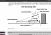
Joel, with the tie rod that close to the upper control arm (height wise) you shouldn’t have it paralell with the LCA.This post is probably a bit premature since the initial setup and alignment of the suspension was done with some very basic tools back on post #320. Front ride height is set at 4.25”. At some point I’ll either buy a tenhulzen alignment setup or take the chassis to an alignment shop before the body is locked down for good.
Fabricated two bump steer spacers and took some measurements. I used a washer stack on the drivers side to get the tie rod angle close to the lower control arm angle. The SLC manual suggests this is the best approach to reduce bump steer.
These are the measurements I got on the driver’s side. I think these numbers are pretty good…
View attachment 125560
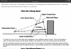
Then used the same sized spacer on the passenger side and it seems I may need to fabricate a slightly taller spacer to get the tie rod closer to the angle of the lower control arm..,
View attachment 125561
I could also just add a single washer on the passenger side which would probably do the trick.
Anway, wondering if most other builders have seen a difference from side to side and is the correct approach to make a taller spacer on the passenger side or is this close enough where it doesn’t really matter.
Check this out. There is a lot to read about bump steer.
Attachments
Joel K
Supporter
Joel, with the tie rod that close to the upper control arm (height wise) you shouldn’t have it paralell with the LCA.
Check this out. There is a lot to read about bump steer.
Thanks Johan, based on this information the tie rod angle will wind up being closer to the top control arm angle than the bottom. Somewhere in between the two. As DaveC recommended, seems a best practice is to run the front suspension through it’s travel and find out how many washers to use then remake the spacers.
Howard Jones
Supporter
"run the front suspension through it’s travel and find out how many washers to use then remake the spacers".
Exactly!
Exactly!
Joel K
Supporter
This is a small update, but for the sake of completeness, including this post on mounting the battery in the rear compartment.
Followed in Dusty’s footsteps and decided to go with a compact LiFePO4 battery. Chose the Antigravity ATX-30-HD which weighs 8 pounds, has 970 Cranking Amps, and 48 Amp Hours of capacity. It has a battery management system which protects from over discharging and over charging plus an integrated battery monitor. Pic of the ATX-30-HD battery…

Mounted it in the rear of the car not far from the starter. Based on what I’ve read, having a short cable to the starter is preferable. Providing as much current as possible to the VW-Graziano starter seems to help on hot starts. Hopefully this battery and placement will reliably start the LT4.
I ordered a Level 7 Motorsports battery case to provide added protection of the battery in the event of an accident or road debris damage. The Level 7 case is really well made, it’s 304 stainless and TIG welded. Here is a pic of the case…

Similar to mounting the overflow coolant tank on the passenger side, decided to use ballast clamps to mount the battery case on the driver side. These clamps are really nice and can securely mount components without drilling holes in the frame. They come with 1/2”-13 threaded holes for mounting things. Pic of the brackets purchased from Southwest speed…

Cut 3/8” aluminum stock to size and drilled a couple holes and chamfered them at 82 degrees…

Here is a pic of the clamps from behind…

Since the 1/2” flathead screw heads are pretty deep(over .25”) I used 3/8” thick aluminum plate, so wanted to pocket it out to lighten it up. Drilled border holes for the areas to pocket out, cut with a jigsaw then trimmed up on the mill. A few hours of work and here is the finished bracket…

Bracket mounted on frame…

Installed the case…

Pic with the Battery installed…

One more item checked off the list. At some point I’ll install heat shielding on the engine side of the ballast brackets.
Followed in Dusty’s footsteps and decided to go with a compact LiFePO4 battery. Chose the Antigravity ATX-30-HD which weighs 8 pounds, has 970 Cranking Amps, and 48 Amp Hours of capacity. It has a battery management system which protects from over discharging and over charging plus an integrated battery monitor. Pic of the ATX-30-HD battery…
Mounted it in the rear of the car not far from the starter. Based on what I’ve read, having a short cable to the starter is preferable. Providing as much current as possible to the VW-Graziano starter seems to help on hot starts. Hopefully this battery and placement will reliably start the LT4.
I ordered a Level 7 Motorsports battery case to provide added protection of the battery in the event of an accident or road debris damage. The Level 7 case is really well made, it’s 304 stainless and TIG welded. Here is a pic of the case…
Similar to mounting the overflow coolant tank on the passenger side, decided to use ballast clamps to mount the battery case on the driver side. These clamps are really nice and can securely mount components without drilling holes in the frame. They come with 1/2”-13 threaded holes for mounting things. Pic of the brackets purchased from Southwest speed…
Cut 3/8” aluminum stock to size and drilled a couple holes and chamfered them at 82 degrees…
Here is a pic of the clamps from behind…
Since the 1/2” flathead screw heads are pretty deep(over .25”) I used 3/8” thick aluminum plate, so wanted to pocket it out to lighten it up. Drilled border holes for the areas to pocket out, cut with a jigsaw then trimmed up on the mill. A few hours of work and here is the finished bracket…
Bracket mounted on frame…
Installed the case…
Pic with the Battery installed…
One more item checked off the list. At some point I’ll install heat shielding on the engine side of the ballast brackets.
Joel K
Supporter
Question regarding the LiFePO batteries - does anyone know the service life of these compared to the traditional lead acid units?
Jeff, I’ve read they can last between 8-10 years although I’ve also read of unsuccessful installs where they went dead during the first year. Like anything they are being improved over time. I’m hoping the battery management system in this battery will keep it healthy for 8-10 years.
I really liked the size and weight and a number of RCR owners have used similar batteries and they started the car reliably even when hot.
Joel K
Supporter
This post covers filling in extra holes in the front compartment panels.
Back on post #199, I mounted a 2010 Camaro SS brake booster in the front compartment. In order for the fans to clear the booster, the radiator needed to be shifted forward about 1”. This left an extra set of holes that needed to be filled in.
Another approach building on the same concept, Geoff found a Mini Cooper brake booster which is a bit shallower and I think would clear the fan shroud as designed without needing to move the radiator forward.
Pic of extra radiator mounting holes that need filling…

Since these panels will be powder coated, they need to be welded instead of using something like an epoxy filler. Throwing caution to the wind I decided to give welding another try. Practiced on some scrap aluminum filling in 1/4” holes and was ready to go. Pic of the four practice holes and ground down one of them to see how it looked. Came out pretty good…

On the driver side panel, also wanted to fill in the brake and clutch reservoir holes since these will not be used. Lots of holes to fill in…

Just slowly welded around the edge of each hole until it started to form a weld pool then inserted 1/8” filler rod and filled in the hole. Once a mound was formed continued to apply heat and blend the mound into the base metal. Flipped the panel over and repeated the process. There was a lot more oxidation than on the practice pieces due to not cleaning out the inside of the holes enough. Pic of the first 4 holes filled in…

Ground those holes down then changed my technique. Inserted an aluminum dowel snugly into each hole instead of using filler rod. Also paid more attention to cleaning out the holes. Heated the dowel up till it melted and added a little 1/16” filler rod as needed, blended the melted dowel around the hole and slowly reduced the heat. This technique was much easier with less oxidation and less heat into the panel to avoid warping…

For the driver side panel I drilled the holes out to 5/16” and used a 5/16” dowel. By drilling the hole out, they were perfectly clean producing much less oxidation in the weld pool. So lesson to be learned. Having perfectly clean parts always makes a big difference when TIG welding aluminum. Pic of the driver side with dowels fitted up…

Finally got nice clean shiny welds…

Ground all the holes down with a Dremel disc then sanded with 220 grit. Certainly good enough for powder coating. Panels are all finished…

While the panels were off, took the opportunity to add some external heat shielding plus drilled holes for the front harness and clutch fluid hose grommets…

Front compartment temporarily put back together. The panels will be powder coated after the front nose hinge is fabricated and before the cooling and AC lines are permanently installed…

Well that was fun and a sense of accomplishment especially when having a good welding result. Planning on doing a separate post on fitting and trimming all the external heat shielding In a future post.
Back on post #199, I mounted a 2010 Camaro SS brake booster in the front compartment. In order for the fans to clear the booster, the radiator needed to be shifted forward about 1”. This left an extra set of holes that needed to be filled in.
Another approach building on the same concept, Geoff found a Mini Cooper brake booster which is a bit shallower and I think would clear the fan shroud as designed without needing to move the radiator forward.
Pic of extra radiator mounting holes that need filling…
Since these panels will be powder coated, they need to be welded instead of using something like an epoxy filler. Throwing caution to the wind I decided to give welding another try. Practiced on some scrap aluminum filling in 1/4” holes and was ready to go. Pic of the four practice holes and ground down one of them to see how it looked. Came out pretty good…
On the driver side panel, also wanted to fill in the brake and clutch reservoir holes since these will not be used. Lots of holes to fill in…
Just slowly welded around the edge of each hole until it started to form a weld pool then inserted 1/8” filler rod and filled in the hole. Once a mound was formed continued to apply heat and blend the mound into the base metal. Flipped the panel over and repeated the process. There was a lot more oxidation than on the practice pieces due to not cleaning out the inside of the holes enough. Pic of the first 4 holes filled in…
Ground those holes down then changed my technique. Inserted an aluminum dowel snugly into each hole instead of using filler rod. Also paid more attention to cleaning out the holes. Heated the dowel up till it melted and added a little 1/16” filler rod as needed, blended the melted dowel around the hole and slowly reduced the heat. This technique was much easier with less oxidation and less heat into the panel to avoid warping…
For the driver side panel I drilled the holes out to 5/16” and used a 5/16” dowel. By drilling the hole out, they were perfectly clean producing much less oxidation in the weld pool. So lesson to be learned. Having perfectly clean parts always makes a big difference when TIG welding aluminum. Pic of the driver side with dowels fitted up…
Finally got nice clean shiny welds…
Ground all the holes down with a Dremel disc then sanded with 220 grit. Certainly good enough for powder coating. Panels are all finished…
While the panels were off, took the opportunity to add some external heat shielding plus drilled holes for the front harness and clutch fluid hose grommets…
Front compartment temporarily put back together. The panels will be powder coated after the front nose hinge is fabricated and before the cooling and AC lines are permanently installed…
Well that was fun and a sense of accomplishment especially when having a good welding result. Planning on doing a separate post on fitting and trimming all the external heat shielding In a future post.
Last edited:
Joel K
Supporter
Time to take a break from the exhaust and final chassis items. Decided to cut out the exterior heat shields.
This post covers how to make simple patterns and cut out and align holes in the heat shield for a nice clean fit. The heat shielding is adhesive backed, but at this time I’m not going to permanently attach it.
Here is a short video on the process…
Here are the supplies and tools used…
1)DEI Matte Black Floor and Tunnel Shield II 50549
2)Large heavy duty scissors
3)Sharp scribe
4)Step drill
5)Various size hole saws
6)Pointed set screws used to locate blind threaded holes
7)Black sharpie
8)Dremel cutting disc
I chose DEI heat shield since it is the maximum heat insulation product they make, it also acts as a sound barrier and comes in a nice matte black finish. All exterior panels will get this applied to them.
1st step is to find an approach to making accurate patterns. I like to use multiple pieces of construction paper and tape them together to form the pattern. This eliminates the need to cut the pattern out precisely. Just butt the paper up to an edge and then overlap it and tape it to the adjoining piece.
Pic of the front foot box pattern and install tools…

Drew the pattern on the back side of the heat shielding…

The material is fairly easy to cut with large, sharp scissors. Tin snipes would work well too, but I like the scissors since they cut the material nice and straight.
Now on to making holes and cut outs. I wanted to do a neat job cutting this material and came up with a few approaches that worked really well.
1)All larger openings - were marked with a sharpie from behind
2)Smaller openings - like M5 screws used the scribe to poked a small hole from behind and drill out from the front. I used a step drill with deep steps.
3)Larger screw holes - Marked each hole center and used a scribe and poked a hole from behind. Drilled out from the front with a step drill with very deep steps. Shallow step drill will not work well since each step doesn’t go all the way through the material. If the hole size needed is the largest on the step drill, then a shallow step drill works ok. The step drills are nice since they cut the aluminum and fiberglass cleanly without getting bound up.
4)Larger round holes - Marked each hole center and used a scribe and poked a hole from behind. Used the step drill to drill a guide hole for the hole saw. Then used a hole saw bit and ran it backward from the aluminum side of the material. While pressing the back side in my hand I could feel when the drill was through all three layers(aluminum, fiberglass, and adhesive backing). It worked great!
5)Blind screw holes - Insert a few sharpened set screws in the chassis and press the material firmly against it. This will poke a hole through the back plastic layer. Then lightly tap the front with a mallet and block of wood causing the set screws to poke through. Use the scribe to further widen the holes and drill them out from the front with a step drill.
Here is a pic of the trimmed up heat shielding for the extended foot box and front of the passenger compartment. You can see some of the various ways to make neat and concise holes and openings in the material…

Pic of front-side panel patterns. Left a small section of the foot box area uncovered. This area is open to cooler air so figure no harm in leaving it uncovered…

Now with the heat shield applied…

Traced the chassis side and interior tub close out panel from a single large sheet of heat shield. Turned out the Chassis passenger side is 48” long and matches the length of the heat shielding sheet...

Inserted the sharpened set screws in the interior tub close out panel to locate the blind holes...

Driver side compartment panel cut and fitted. Used the sharpened set screw technique to locate the blind holes. The screws lined up perfectly for the brake lines and tub close out panel…

Rear bulkhead, fuel tank close out panels, and lower frame rail all get heat shielding…

3/4 view from the front…

That was a lot of fun. I’ll permanently attach them to the chassis after I know, no more holes need to be drilled. I’ll seal the edges up with either matte black flashing tape or urethane chassis sealer.
This post covers how to make simple patterns and cut out and align holes in the heat shield for a nice clean fit. The heat shielding is adhesive backed, but at this time I’m not going to permanently attach it.
Here is a short video on the process…
Here are the supplies and tools used…
1)DEI Matte Black Floor and Tunnel Shield II 50549
2)Large heavy duty scissors
3)Sharp scribe
4)Step drill
5)Various size hole saws
6)Pointed set screws used to locate blind threaded holes
7)Black sharpie
8)Dremel cutting disc
I chose DEI heat shield since it is the maximum heat insulation product they make, it also acts as a sound barrier and comes in a nice matte black finish. All exterior panels will get this applied to them.
1st step is to find an approach to making accurate patterns. I like to use multiple pieces of construction paper and tape them together to form the pattern. This eliminates the need to cut the pattern out precisely. Just butt the paper up to an edge and then overlap it and tape it to the adjoining piece.
Pic of the front foot box pattern and install tools…
Drew the pattern on the back side of the heat shielding…
The material is fairly easy to cut with large, sharp scissors. Tin snipes would work well too, but I like the scissors since they cut the material nice and straight.
Now on to making holes and cut outs. I wanted to do a neat job cutting this material and came up with a few approaches that worked really well.
1)All larger openings - were marked with a sharpie from behind
2)Smaller openings - like M5 screws used the scribe to poked a small hole from behind and drill out from the front. I used a step drill with deep steps.
3)Larger screw holes - Marked each hole center and used a scribe and poked a hole from behind. Drilled out from the front with a step drill with very deep steps. Shallow step drill will not work well since each step doesn’t go all the way through the material. If the hole size needed is the largest on the step drill, then a shallow step drill works ok. The step drills are nice since they cut the aluminum and fiberglass cleanly without getting bound up.
4)Larger round holes - Marked each hole center and used a scribe and poked a hole from behind. Used the step drill to drill a guide hole for the hole saw. Then used a hole saw bit and ran it backward from the aluminum side of the material. While pressing the back side in my hand I could feel when the drill was through all three layers(aluminum, fiberglass, and adhesive backing). It worked great!
5)Blind screw holes - Insert a few sharpened set screws in the chassis and press the material firmly against it. This will poke a hole through the back plastic layer. Then lightly tap the front with a mallet and block of wood causing the set screws to poke through. Use the scribe to further widen the holes and drill them out from the front with a step drill.
Here is a pic of the trimmed up heat shielding for the extended foot box and front of the passenger compartment. You can see some of the various ways to make neat and concise holes and openings in the material…
Pic of front-side panel patterns. Left a small section of the foot box area uncovered. This area is open to cooler air so figure no harm in leaving it uncovered…
Now with the heat shield applied…
Traced the chassis side and interior tub close out panel from a single large sheet of heat shield. Turned out the Chassis passenger side is 48” long and matches the length of the heat shielding sheet...
Inserted the sharpened set screws in the interior tub close out panel to locate the blind holes...
Driver side compartment panel cut and fitted. Used the sharpened set screw technique to locate the blind holes. The screws lined up perfectly for the brake lines and tub close out panel…
Rear bulkhead, fuel tank close out panels, and lower frame rail all get heat shielding…
3/4 view from the front…
That was a lot of fun. I’ll permanently attach them to the chassis after I know, no more holes need to be drilled. I’ll seal the edges up with either matte black flashing tape or urethane chassis sealer.
Nice write up Joel !!
Thank You.
Regards Brian
Thank You.
Regards Brian
Neil
Supporter
Does the DEI heat shield burn?Time to take a break from the exhaust and final chassis items. Decided to cut out the exterior heat shields.
This post covers how to make simple patterns and cut out and align holes in the heat shield for a nice clean fit. The heat shielding is adhesive backed, but at this time I’m not going to permanently attach it.
Here is a short video on the process…
Here are the supplies and tools used…
1)DEI Matte Black Floor and Tunnel Shield II 50549
2)Large heavy duty scissors
3)Sharp scribe
4)Step drill
5)Various size hole saws
6)Pointed set screws used to locate blind threaded holes
7)Black sharpie
8)Dremel cutting disc
I chose DEI heat shield since it is the maximum heat insulation product they make, it also acts as a sound barrier and comes in a nice matte black finish. All exterior panels will get this applied to them.
1st step is to find an approach to making accurate patterns. I like to use multiple pieces of construction paper and tape them together to form the pattern. This eliminates the need to cut the pattern out precisely. Just butt the paper up to an edge and then overlap it and tape it to the adjoining piece.
Pic of the front foot box pattern and install tools…
View attachment 127260
Drew the pattern on the back side of the heat shielding…
View attachment 127251
The material is fairly easy to cut with large, sharp scissors. Tin snipes would work well too, but I like the scissors since they cut the material nice and straight.
Now on to making holes and cut outs. I wanted to do a neat job cutting this material and came up with a few approaches that worked really well.
1)All larger openings - were marked with a sharpie from behind
2)Smaller openings - like M5 screws used the scribe to poked a small hole from behind and drill out from the front. I used a step drill with deep steps.
3)Larger screw holes - Marked each hole center and used a scribe and poked a hole from behind. Drilled out from the front with a step drill with very deep steps. Shallow step drill will not work well since each step doesn’t go all the way through the material. If the hole size needed is the largest on the step drill, then a shallow step drill works ok. The step drills are nice since they cut the aluminum and fiberglass cleanly without getting bound up.
4)Larger round holes - Marked each hole center and used a scribe and poked a hole from behind. Used the step drill to drill a guide hole for the hole saw. Then used a hole saw bit and ran it backward from the aluminum side of the material. While pressing the back side in my hand I could feel when the drill was through all three layers(aluminum, fiberglass, and adhesive backing). It worked great!
5)Blind screw holes - Insert a few sharpened set screws in the chassis and press the material firmly against it. This will poke a hole through the back plastic layer. Then lightly tap the front with a mallet and block of wood causing the set screws to poke through. Use the scribe to further widen the holes and drill them out from the front with a step drill.
Here is a pic of the trimmed up heat shielding for the extended foot box and front of the passenger compartment. You can see some of the various ways to make neat and concise holes and openings in the material…
View attachment 127252
Pic of front-side panel patterns. Left a small section of the foot box area uncovered. This area is open to cooler air so figure no harm in leaving it uncovered…
View attachment 127253
Now with the heat shield applied…
View attachment 127254
Traced the chassis side and interior tub close out panel from a single large sheet of heat shield. Turned out the Chassis passenger side is 48” long and matches the length of the heat shielding sheet...
View attachment 127255
Inserted the sharpened set screws in the interior tub close out panel to locate the blind holes...
View attachment 127256
Driver side compartment panel cut and fitted. Used the sharpened set screw technique to locate the blind holes. The screws lined up perfectly for the brake lines and tub close out panel…
View attachment 127257
Rear bulkhead, fuel tank close out panels, and lower frame rail all get heat shielding…
View attachment 127258
3/4 view from the front…
View attachment 127259
That was a lot of fun. I’ll permanently attach them to the chassis after I know, no more holes need to be drilled. I’ll seal the edges up with either matte black flashing tape or urethane chassis sealer.
Similar threads
- Replies
- 15
- Views
- 1K