
- Forums
- GT40 Replica Manufacturers' Corner
- RCR Forum - RCR40/SLC/917/Superlite Aero
- The SLC Clubhouse
You are using an out of date browser. It may not display this or other websites correctly.
You should upgrade or use an alternative browser.
You should upgrade or use an alternative browser.
Ken's SLC build thread
- Thread starter KENS80V
- Start date
As always, nicely done Ken.
Regards Brian
Regards Brian
Ken Roberts
Supporter
Finished modifying the outer door handles so they lock/unlock with a key. Thanks go to Bill Phillips for coming up with the idea and others who refined it.

Last edited:
Ken Roberts
Supporter
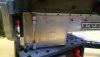
The pencil is pointing to the studs I added that have a swiveling eyelet at the top. These little suckers are very expensive but I thought necessary for a long trouble free life.

 www.mcmaster.com

McMaster-Carr
McMaster-Carr is the complete source for your plant with over 595,000 products. 98% of products ordered ship from stock and deliver same or next day.
Ken Roberts
Supporter
The pencil is pointing to the stainless 1/8" welding rod I bent to fit the stock plastic pivot joint. I smashed the end with multiple blows of a hammer in order to get enough width to drill a hole for the spring. Here is the part number for the spring.
www.mcmaster.com

McMaster-Carr
McMaster-Carr is the complete source for your plant with over 595,000 products. 98% of products ordered ship from stock and deliver same or next day.
Last edited:
Ken Roberts
Supporter
Here are the cables and eyelets getting ready for use in the doors for the attachment to the bear claw latches. Not the cheapest solution by far at $15 each. I cut them longer than needed and will put them in place and then shorten the one end to fit. The eyelets were purchased from Summit Racing. The 5/64" cable is from McMaster Carr. I had to slightly drill out the holes in the eyelets to fit the cable size. I'll try and use the rest of the cable for the inner door handle function. (I'm going to attempt to use rods instead first)
TIP- cut the cable carefully or it will be difficult to feed in the eyelet. I wrapped the cable tightly first with tape.
www.mcmaster.com
 www.jegs.com

TIP- cut the cable carefully or it will be difficult to feed in the eyelet. I wrapped the cable tightly first with tape.
McMaster-Carr
McMaster-Carr is the complete source for your plant with over 595,000 products. 98% of products ordered ship from stock and deliver same or next day.
Competition Engineering 8-Point Roll Bars for Imports - JEGS High Performance
Competition Engineering 8-Point Roll Bars for Imports
Last edited:
Ken Roberts
Supporter
The new Miata door handles came with mounting studs that were an appropriate length for sheet metal but too short for the thicker fiberglass panels. I purchased 4 metric threaded rods and custom cut two of them for clearance (pencil tip is pointing to the studs that need to be shortened).
https://www.mcmaster.com/93325a417

https://www.mcmaster.com/93325a417
Ken Roberts
Supporter
Here is a picture showing where the cable will get attached in the near future. It's best if its allowed to pivot freely. I'll come up with a solution after the holidays.

Last edited:
Ken Roberts
Supporter
The pencil is pointing to the stainless plates. They're .060" thick. I chose stainless so that it will still pivot smoothly in the future. I wanted it strong to resist a forced entry. The picture shows them in the locked position.
. https://www.mcmaster.com/8983k115

. https://www.mcmaster.com/8983k115
Last edited:
Ken Roberts
Supporter
I removed the inner door handle lock/unlock mechanism and just glued the slide in the unlock position. Just trying to keep things simple where possible.

Last edited:
Ken Roberts
Supporter
My inner door handle bezels were weathered and one had cracks where the screw fastened it in place. New ones are available on ebay for $14 a pair.
The screws were missing from my set. They are a M4 x .7mm x 12mm flat head
www.mcmaster.com

The screws were missing from my set. They are a M4 x .7mm x 12mm flat head
McMaster-Carr
McMaster-Carr is the complete source for your plant with over 595,000 products. 98% of products ordered ship from stock and deliver same or next day.
Ken Roberts
Supporter
I see the GT-R uses Miata inner door handles but what is used for the outer doors?
Ken
Question. The two ends white and orange with the “z” shaped bracket, does yours hit the interior fiberglass once mounted? Mine did and I had to modify my bracket. I also have a problem with the spring pulling the tumbler around sometimes so it repositions into the locked position.
If yours works, then I need to modify mine again to imitate your set up. Mines very similar, but I do have a little issue. PS I managed to bend some solid rods in lieu of wire, but I don’t think it makes much difference. It opens the door.
Ken Roberts
Supporter
Ken
Question. The two ends white and orange with the “z” shaped bracket, does yours hit the interior fiberglass once mounted? Mine did and I had to modify my bracket. I also have a problem with the spring pulling the tumbler around sometimes so it repositions into the locked position.
If yours works, then I need to modify mine again to imitate your set up. Mines very similar, but I do have a little issue. PS I managed to bend some solid rods in lieu of wire, but I don’t think it makes much difference. It opens the door.
I'll update as soon as I get a chance to install them Dan. Cam said recently that one side fit without any interference and the other side needed a slight sanding to fit. The beauty of my design is the fact the spring is smaller in diameter and pivots freely without brushing against the arm.
UPDATE-mine fit without needing any trimming as described above.
Last edited:
Ken Roberts
Supporter
Those are spacers installed by the factory. I believe, from memory, they are approx 1/4” thick. The main L bracket had one as well.
Joel K
Supporter
Those are spacers installed by the factory. I believe, from memory, they are approx 1/4” thick. The main L bracket had one as well.
Thanks Ken, steel or aluminum? I don’t seem to see them on other builds. Wonder if they were used for spacing or to mount the rack more securely.
Ken Roberts
Supporter
They are made from aluminum. They spaced the rack 1/4” out from the bulkhead. I assumed all cars had them......hmmmmm
Joel K
Supporter
Ken,
The reason I ask is if the steering box is mounted with all 4 bolts, the rear two bolts will get very close to the step/corner weld of the extended footbox structure so wondering if I should space it out. Stephan confirmed he does not have a spacer and does not have the extended footbox. Here are pics of my work in process and the arrows point to my area of concern....


I can email RCR in the morning, just figure I’d reach out to get your perspective.
The reason I ask is if the steering box is mounted with all 4 bolts, the rear two bolts will get very close to the step/corner weld of the extended footbox structure so wondering if I should space it out. Stephan confirmed he does not have a spacer and does not have the extended footbox. Here are pics of my work in process and the arrows point to my area of concern....
I can email RCR in the morning, just figure I’d reach out to get your perspective.
Similar threads
- Replies
- 5
- Views
- 1K
- Replies
- 1
- Views
- 2K