
- Forums
- GT40 Replica Manufacturers' Corner
- RCR Forum - RCR40/SLC/917/Superlite Aero
- The SLC Clubhouse
You are using an out of date browser. It may not display this or other websites correctly.
You should upgrade or use an alternative browser.
You should upgrade or use an alternative browser.
Kurt H (hoffkm) SL-C build thread
- Thread starter Hoffkm12
- Start date
Steven Lobel
Supporter
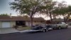
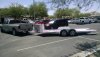
I like my kwik-load tilt trailer. I did add extra locking pins for the roller mechanism to the central lock. Extra security. And extra things on the check list to do before loading/unloading.
Yeah I guess it’s because I grew up in a towing company. Never had a tow in a fixed trailer, only tilt ones where people drive the car on and forgot to pin. Or hydro ones where the piston broke up those were always fun.
I remember when I first saw the airbag drop trailers at Sema. all I thought to myself is well great idea but man people are gonna mess this up.
I remember when I first saw the airbag drop trailers at Sema. all I thought to myself is well great idea but man people are gonna mess this up.
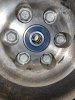
I have been stuck figuring out and gathering electrical components, I felt the need to accomplish some task, so I pressed the pilot bearing, very happy that it fits nice and tight, major relief.
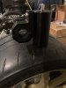
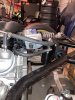
I also followed Cams lead on the PVC oil catch can on the dirty side , found a nice set of brackets to fit over the rear support bar. Very happy how it turned out , needed to use bigger screws, rethread the can, modify the holes on the brackets and trim the rubber a bit.
I did not have the right size oetiker clamps, so worm clamps will have to do for now. Now I feel better I accomplished a task. Keep on.
Attachments
Hi Kurt,
Can you let me know how much clearance there is with your seat bracket design between the interior tub and the rear outside of the seat bracket? I need to finalize my design over the next month. Thanks!
View attachment 109785
Joel,
Your timing is perfect. Last week I fit my center console so I am now "95%" certain of my final seat location. My bracket design (which is a huge plagiarism of your design) gives me 3 1/2" at the front and rear of the drivers side bracket (gentleman's seat) between it and the tub and 4" on the passenger side (standard seat). The extra clearance is very helpful in getting in and out of the car (which I am a long way from mastering gracefully). There is just enough room for my foot between the bracket and tub.
I have a drawing of my bracket if it helps you in any way.
Joel K
Supporter
Joel,
Your timing is perfect. Last week I fit my center console so I am now "95%" certain of my final seat location. My bracket design (which is a huge plagiarism of your design) gives me 3 1/2" at the front and rear of the drivers side bracket (gentleman's seat) between it and the tub and 4" on the passenger side (standard seat). The extra clearance is very helpful in getting in and out of the car (which I am a long way from mastering gracefully). There is just enough room for my foot between the bracket and tub.
I have a drawing of my bracket if it helps you in any way.
Thanks Kurt, I like the way you bent the brackets with the dual 45 Degree angles. They look right and are functional. Also making it out of steel is good so you can weld nuts on top and use a round head bolt from the bottom to secure it.
I need a good 4” on the driver side so thinking of a couple mods to the seat itself. Would really appreciate it to see the drawings.
Joel,
Depending on how much you are tilting your seat and how low you have the back placed you may be able to offset the brackets another 1/2" to get the 4" spacing. I am rather "tall in the torso" so I need the rear of my seat basically sitting on the floor with it reclined as much as possible without the front of the seat shoving much legs up into the bottom of the steering wheel. It was a balancing act but I think I have it nailed (for me to fit at least). If you want to use my print with any changes I can generated an updated drawing for you, just let me know.
I attached a .pdf file of my seat bracket drawing. I will take a screen shot tomorrow when I have access to my CAD station at work to show you how I plan to attach these into the car. I do not care for how "flexible" the floor is where the seats mount. My plan is to sandwich the floorpan between my steel bracket and a piece of 5/16 x 3/4 steel bar stock with 5/16-24 threaded holes in the bar stock. This should stiffen the floor and give me a steel "rub rail" under the chassis instead of having button head fasteners protruding below the floor. My brackets are slotted for adjustment of the seat back and forth and the tapped bar will make loosening the mounting bolts a one man job to adjust the seat.
Attachments
Joel K
Supporter
Kurt, I focused on the pdf instead of reading your explanation so sorry for the dumb question so deleted the post.
Anyway, looks like 3.75” is enough room. Probably the only change would be to have the seat more upright, but I have those dimensions when I mounted the seat with the stock brackets. Please post the install info when you have a chance.
Anyway, looks like 3.75” is enough room. Probably the only change would be to have the seat more upright, but I have those dimensions when I mounted the seat with the stock brackets. Please post the install info when you have a chance.
Last edited:
Joel,
Here is a screen shot of the CAD model for my seat brackets and mounting/skid rails.

The pieces on the top of the brackets are a concept of a filler plate to mount the seats to the brackets. The plate is aluminum and fits into the recess in the seats to spread out the load better than a fender washer. Even with the largest fender washer I could fit into the recess I still heard the fiberglass "crunching" when I tightened the mounting bolts. The slots leave room to run my five point harness thru openings in the side of the seats.
If you have any questions let me know.
Here is a screen shot of the CAD model for my seat brackets and mounting/skid rails.
The pieces on the top of the brackets are a concept of a filler plate to mount the seats to the brackets. The plate is aluminum and fits into the recess in the seats to spread out the load better than a fender washer. Even with the largest fender washer I could fit into the recess I still heard the fiberglass "crunching" when I tightened the mounting bolts. The slots leave room to run my five point harness thru openings in the side of the seats.
If you have any questions let me know.
It has been quite some time since my last progress update and I have accomplished quite a bit on the SL-C.
1) I Cerakoted the exhaust. I sprayed them outside this time and let them cure outdoors so the fumes did not want to kill me this time..
2) I finished mounting the oil cooler and fan.
3) I fabricated and installed my CAI.
4) I installed and wrapped the exhaust in DEI titanium header wrap
5) I finished installing and plumbing the Stanceparts lift system
6) I removed the shocks and installed solid ride height spacers to prepare for checking and setting up the suspension
7) I final fit the center console and seats
8) I tidied up the main power wiring to allow it to fit under the close out panels I have decided to add to both sides of the engine bay (to hide the wiring, fuel system plumbing, and oil cooler)
9) I installed my 3D printed rear view camera mount on the top of the spider. I will smooth this into the spider during the bodywork phase
10) I determined where and how my subwoofer would fit into the cockpit and and made a sub box for it
11) I painted the brake calipers using POR15 caliper paint, applied "Brembo" labels to them, clearcoated over the labels for protection, and installed the brakes. I have used POR15 caliper paint on previous projects with good success. Stick with what you know.
12) I finalized my gauge and switch layout for the dash
13) I fabricated my pedal slider assembly and installed it. I am glad this is done, working inside the footbox is no easy task.
14) I bled the brakes and clutch. I first tried using my vacuum bleeder setup but could not get a good bleed this way. I believe the residual valves made vacuum bleeding more difficult. I purchased a Motive Products pressure bleeder and must say that is the way to go whenever you are bleeding brakes on any vehicle. Easy peasy!
15) I started laying out my AC plumbing taking ques from how Joel has done his. Back working in the footbox again! Ugh! As my father in law put it, the footbox isn't too small, there is just too much of me!
More progress pics


Next on the agenda is finishing the AC plumbing, taking the suspension apart, polishing everything, applying Sharkhyde protectant, doing an alignment, temporarily wiring in some switches in the dash, and then GO KART TEST!!
It was two years ago this coming November 26th that my wife and I made a trip up to see Fran and tour RCR. My goal is to go kart test on that same date this year.
It was two years ago this coming November 26th that my wife and I made a trip up to see Fran and tour RCR. My goal is to go kart test on that same date this year.
Similar threads
- Replies
- 12
- Views
- 885