Man..... talk about some progress! I have absolutely nothing of interest to add, other than I think the Brembo circle logo only on the e-brake caliper would look better for some reason. Unsure why, just stood out to the non-builder in me.
I've kicked around sub idea for mine as well, I think may have room under my dash to potentially fit a class-d 5-channel since the Kappas really shine with more power from my experience (albeit 20yrs ago), plus would need a sub amp. I was told about vehicle "micro amps" are even smaller, but haven't looked into them (if they are a new thing). Never tested any amp under the dash, just guessing.
I've kicked around sub idea for mine as well, I think may have room under my dash to potentially fit a class-d 5-channel since the Kappas really shine with more power from my experience (albeit 20yrs ago), plus would need a sub amp. I was told about vehicle "micro amps" are even smaller, but haven't looked into them (if they are a new thing). Never tested any amp under the dash, just guessing.


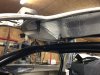
") . I did have to shim the body up some as noted above but it fits perfectly. The only issue now is that the shims have raised the lower front portion of the body off of the aluminum side skirts but I will address that issue next. I may just shim the rear of the spider to match the front and then "pull" the sides of the spider down to the side skirts. Have not decided on my final course of action just yet.
. I did have to shim the body up some as noted above but it fits perfectly. The only issue now is that the shims have raised the lower front portion of the body off of the aluminum side skirts but I will address that issue next. I may just shim the rear of the spider to match the front and then "pull" the sides of the spider down to the side skirts. Have not decided on my final course of action just yet.