Hi,
I have a habit of making things more difficult for myself than need be.. I could just copy an existing frame and be happy with it, buuuut... accepting something as it is has never been my strong suit")
I'll also start with stating that my GT40 dreams are not to build a "replica". I love the car for it's stylish lines and history. So the bodylines will likely be the only thing keeping it close to the original (I'm also opting for the less common MK2 body, but with a 50mm widening per side).
Alright. Frame! For starters I'll be using conventional double wishbone suspension in the back. I will probably try to use a push arm suspension setup both front and rear. I'm also using an Audi V8 which is short! Really short, only about 22-23 inches long.. And most likely a flipped Porsche G86 or 96 gearbox (in the model right now I have a flipped 01E wich is close enough for now)
I have let myself be inspired by the Ultima GTR chassis and, the king of ground effects, Porsche 956/962 chassis. Currently I've only played around in Fusion 360 putting pipes between known limits and points. So I'll have to rework everything later on. This in mainly to figure out a concept to work with, and I was hoping that the knowledge in this forum could help find areas where I can use the piping in smarter ways, or to steer me in the right direction with parts that are fundamentaly wrong
Pics.
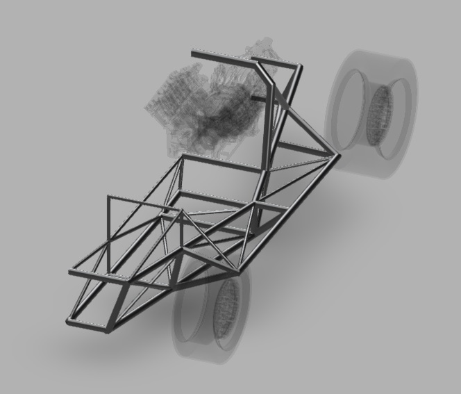
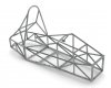
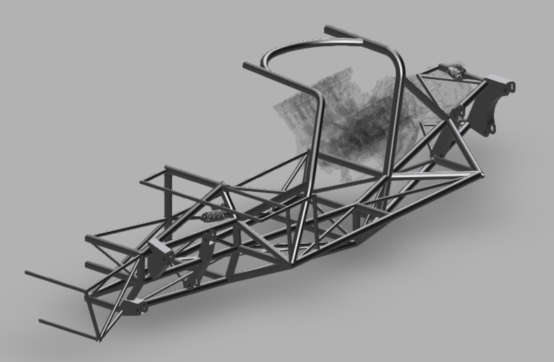
My main goals when doing this has been to create more footwell width, a frame as stiff as "possible", and a frame that is light. It will feature a front roll hoop attached to the rear further on to help with that stiffness.
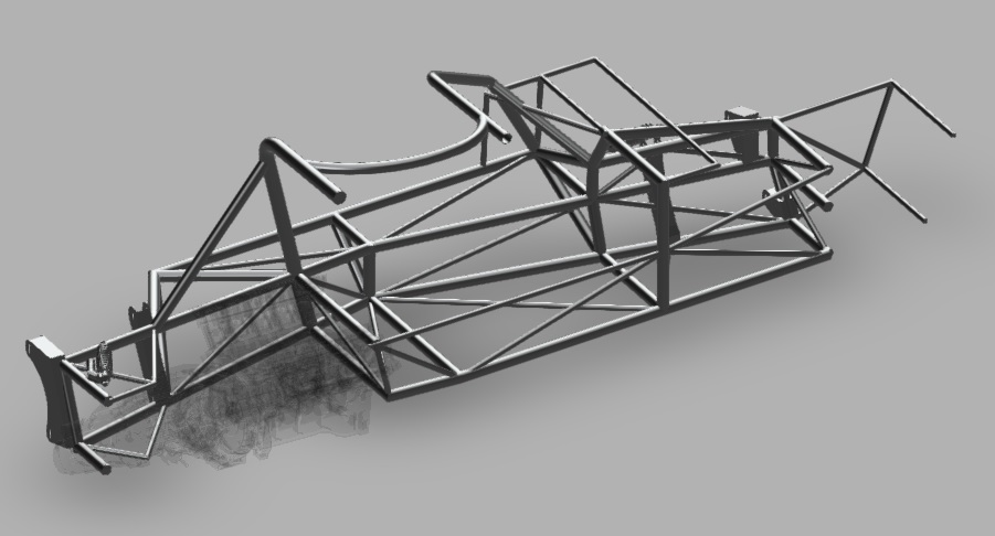
Design thoughts have circled around using as long straight tubes as possible to minimize welding, and trying to see the chassis as a strong centersection with extras to "fill out" the bodywork (and supply extra rigity). A 962 chassis for example does not have the extra structure over the tanks that the GT40 has that can provide extra rigity. However, the way I have designed this at the moment will probably give me four fueltanks instead of two..
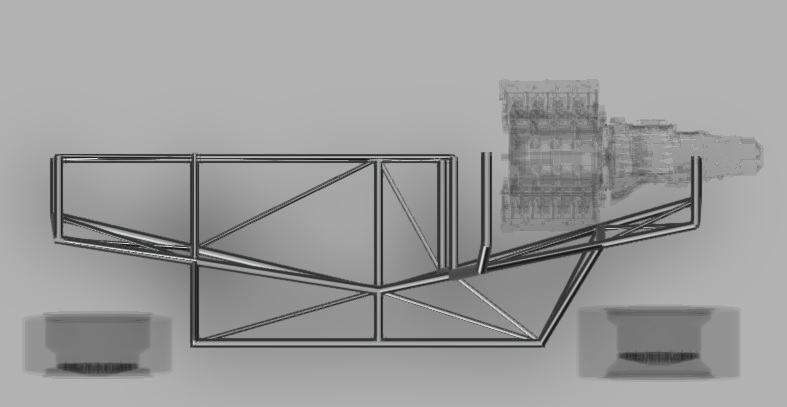
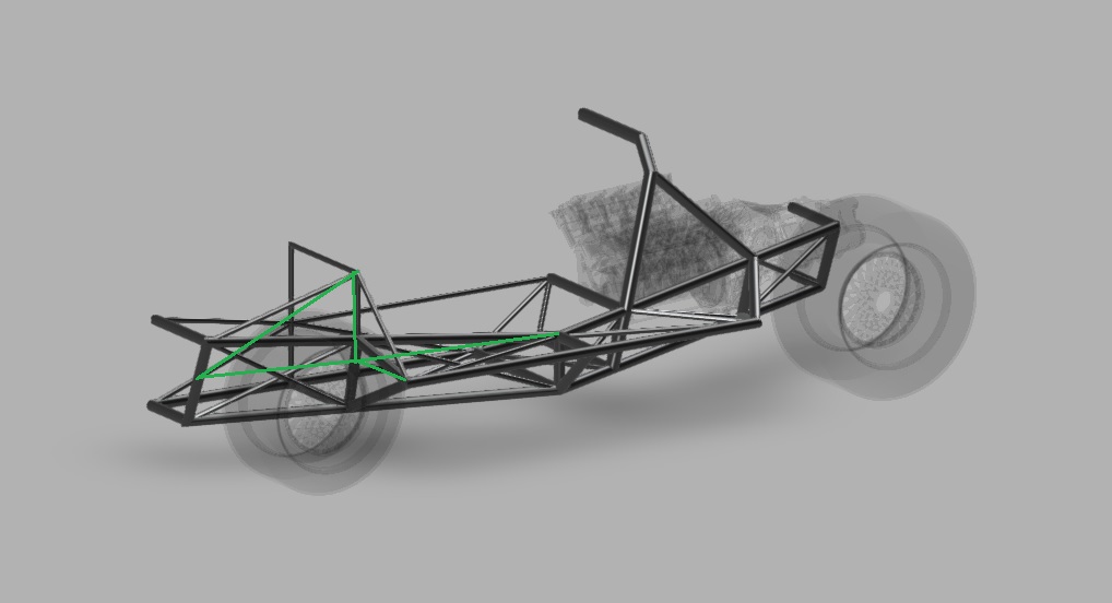
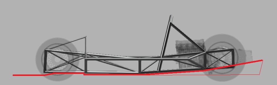
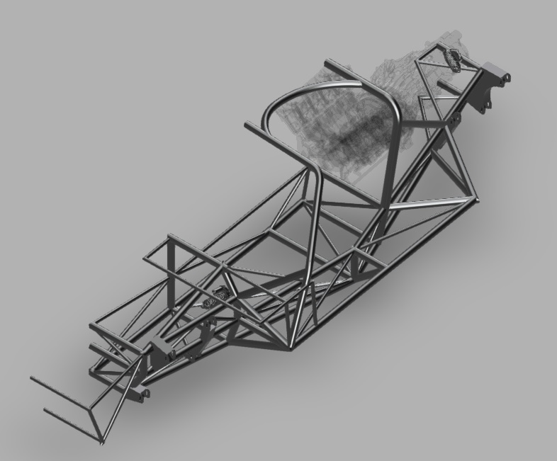
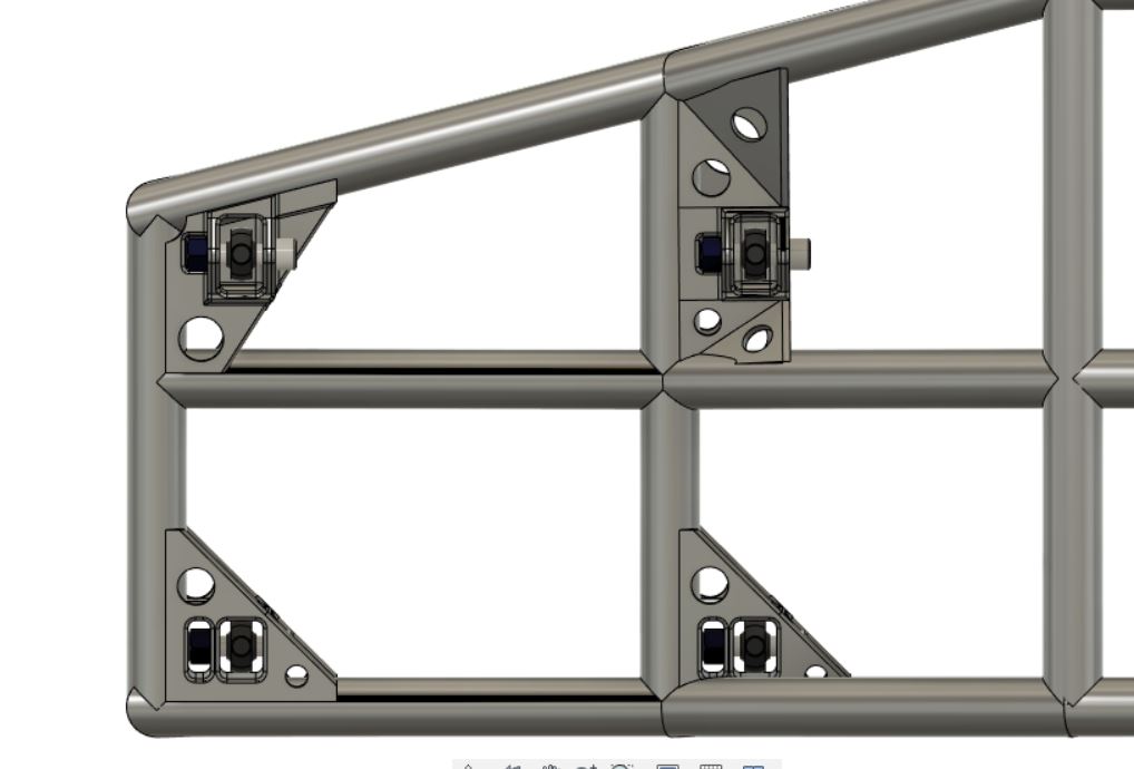
I'm not particularly fond of how the front and rear halves meet and the angle they create. So I will place the upper pipe more parallell to the ground, more like the image below (see green lines). That would also flatten the front half of the door sill.
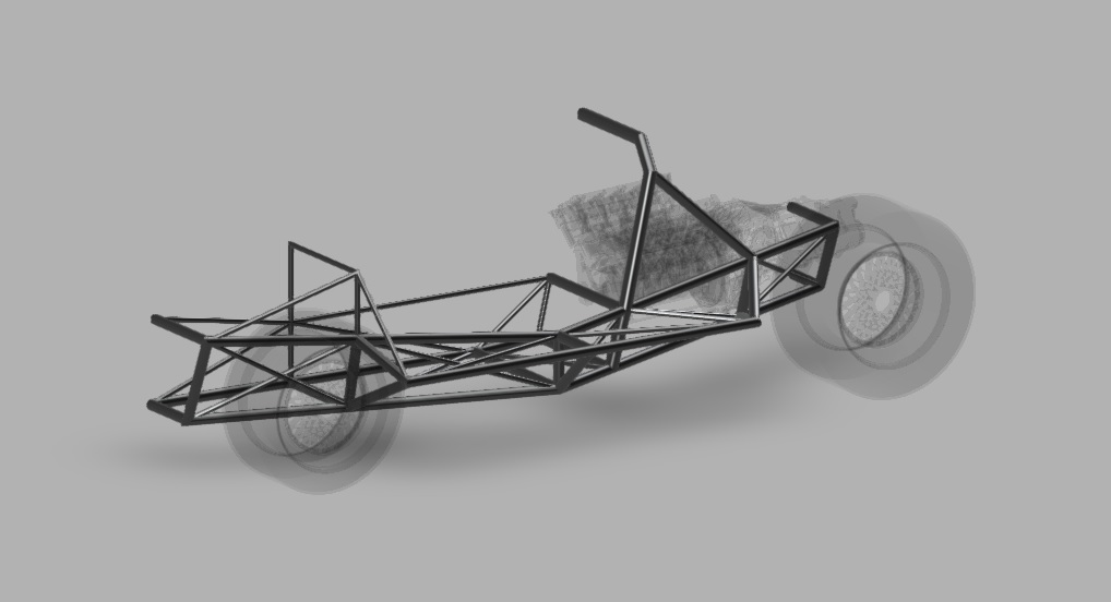
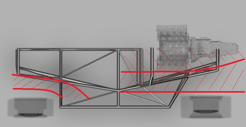
As you can see the frame takes an upward angle from about the middle of the car. The engine and trans is also tilted about 3 degrees to follow this inclination. Not as visible is that the front half of the frame is also tilted downwards (from the front). This is to make room for a front end diffuser. The plan is then to steer the air from the front diffuser out towards the sides. How to get this nice and tidy I do not yet know..
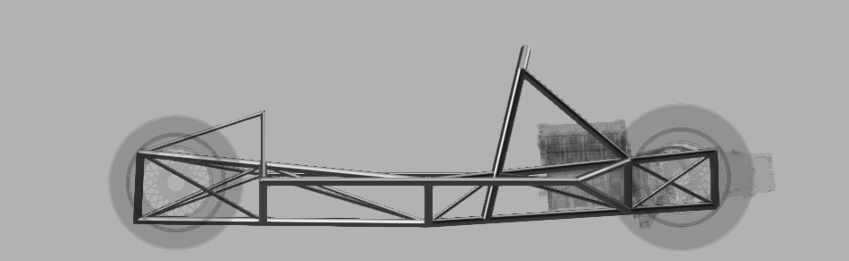
The underside angles of the car are also inspired from the 962 and the reason is to make space for a venturi tunnel that extends as far in under the car as possible. The front aero could just aswell end up being just a nice splitter and a flat undertray but the rear I feel quite happy with at the moment as a concept.
As stated this is still in the early stages. I'm estimating I will need about a year of CAD before I'm ready to start chopping tubes. I've waited to start this project for several years due to the lack of a workshop close by but now that I have a space I can use just a few metres from my door it's finaly time to get serious about this
I have a habit of making things more difficult for myself than need be.. I could just copy an existing frame and be happy with it, buuuut... accepting something as it is has never been my strong suit
I'll also start with stating that my GT40 dreams are not to build a "replica". I love the car for it's stylish lines and history. So the bodylines will likely be the only thing keeping it close to the original (I'm also opting for the less common MK2 body, but with a 50mm widening per side).
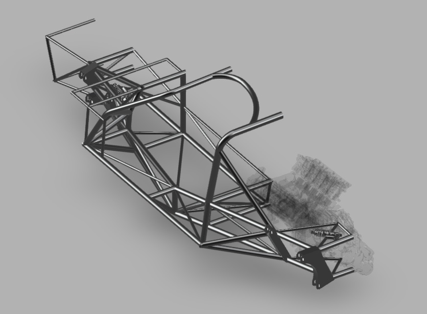
Alright. Frame! For starters I'll be using conventional double wishbone suspension in the back. I will probably try to use a push arm suspension setup both front and rear. I'm also using an Audi V8 which is short! Really short, only about 22-23 inches long.. And most likely a flipped Porsche G86 or 96 gearbox (in the model right now I have a flipped 01E wich is close enough for now)
I have let myself be inspired by the Ultima GTR chassis and, the king of ground effects, Porsche 956/962 chassis. Currently I've only played around in Fusion 360 putting pipes between known limits and points. So I'll have to rework everything later on. This in mainly to figure out a concept to work with, and I was hoping that the knowledge in this forum could help find areas where I can use the piping in smarter ways, or to steer me in the right direction with parts that are fundamentaly wrong
Pics.
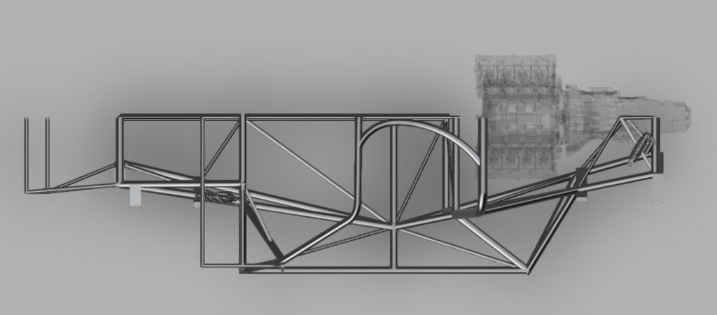
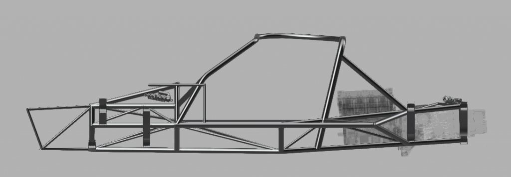
My main goals when doing this has been to create more footwell width, a frame as stiff as "possible", and a frame that is light. It will feature a front roll hoop attached to the rear further on to help with that stiffness.
Design thoughts have circled around using as long straight tubes as possible to minimize welding, and trying to see the chassis as a strong centersection with extras to "fill out" the bodywork (and supply extra rigity). A 962 chassis for example does not have the extra structure over the tanks that the GT40 has that can provide extra rigity. However, the way I have designed this at the moment will probably give me four fueltanks instead of two..
I'm not particularly fond of how the front and rear halves meet and the angle they create. So I will place the upper pipe more parallell to the ground, more like the image below (see green lines). That would also flatten the front half of the door sill.
As you can see the frame takes an upward angle from about the middle of the car. The engine and trans is also tilted about 3 degrees to follow this inclination. Not as visible is that the front half of the frame is also tilted downwards (from the front). This is to make room for a front end diffuser. The plan is then to steer the air from the front diffuser out towards the sides. How to get this nice and tidy I do not yet know..
The underside angles of the car are also inspired from the 962 and the reason is to make space for a venturi tunnel that extends as far in under the car as possible. The front aero could just aswell end up being just a nice splitter and a flat undertray but the rear I feel quite happy with at the moment as a concept.
As stated this is still in the early stages. I'm estimating I will need about a year of CAD before I'm ready to start chopping tubes. I've waited to start this project for several years due to the lack of a workshop close by but now that I have a space I can use just a few metres from my door it's finaly time to get serious about this
")