Marko's GTD (I think) 40

Ian Anderson

Lifetime Supporter
Stick an air filter and on it.
And test with a straight edge side to side and top to bottom.

If the straight edge clears you are good to go

Ian
 

Terry Oxandale

Skinny Man
Hi

That's a very good point Terry. The clevis pins are one of the first parts I had done for the Ford, so I was still getting into the whole "think it through" thing. It does make perfect sense what you're saying and I will gladly take your advice. I do have a question however. The pin has to have an angle to it. If you used a rectangular pipe it has 90 deg angles on it, as I see you did by your photo. If that's the case the bolt itself has to be tilted at an angle as to acommodate for the angle between the clevis pin - trailing arm pickup point line and a line in the upright parallel to the centerline of the car. Or did you simply bend the tube you used for the clevis to an appropriate angle?

You've noticed. While your clevises are vertically oriented (the flats are vertical), mine are horizontally oriented, so the photo you see of mine are from the side view, not top view, thus I was able to cut the angle out using the rectangular tubing, yet have the bolt head snug and properly fitting in the clevis.
 
Hi guys

Just a short update.

Stuck a filter on it and everything seems good with the circular filter at least.

I was finishing another project lately and had college graduation so didnt have much time for the Ford. I did however install this awesome steering wheel and pedal box. Dont mind the USB cables sticking out of them. Im testing the fly-by-wire mode.
 

Attachments

  • IMG_20161007_083834.jpg
    IMG_20161007_083834.jpg
    80.2 KB · Views: 349
  • IMG_20161007_083819.jpg
    IMG_20161007_083819.jpg
    71.4 KB · Views: 328
Hi guys

Time for the news. I did a lot of thinking, planning, researching and talking to some people and made some big decisions.

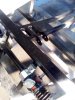
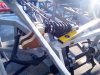
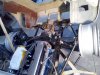
I'll start with what I did. The rear suspension is complete except for two things. I need to relocate the upper shock pickup points further down and I have to redo the clevis pins (cheers Terry). I finished with all the stainless spacers and got everything nice and level and straight and parallel.

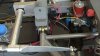
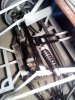
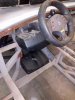
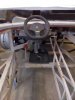
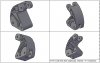
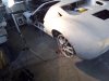
Today I moved to the front end. After fiddling for a while with the front shock pickup points I decided to scrap that idea completely. Instead I decided to install the shocks almost horizontally close to vehicle centerline. The force from the wishbone will be transferred to the aluminium crank bell via a titanium pushrod. The crank bell will in turn operate the shock. Sort of what can be seen in F1 cars. I made a CAD model of the crank bell and it is going on stress analysis tomorrow. Apart from the lower unsprung weight benefit, which is the main reason why I decided to go this route, the shock settings will be easier to adjust because of their position. Although much less relevant than the open suspension cars, the aerodynamics behind the rim will be smoother without that lump of a coil. As an added benefit, it will look mighty sexy :)

Another big decision is to drop the Gulf livery I was planning to do and not stick to the original as much as I was going to. Instead I decided to implement many aircraft parts, namely RAF aircraft. Me being an aircraft engineer, this course of action seemed natural, and frankly I have no idea why I haven't thought of that before.

Anyway, I'm installing the pitotstatic and gyro system, probably both from a Tornado, altough Harriers and Vulcans are an option as well. All the instruments will be replaced by avionics. I'm also installing instruments like altimeter, magnetic compass, artificial horizont, turn indicator and maybe a few more. Engine instruments will come from WW2 piston warbirds (hopefully Spitfire) and will include EGT, CHT, oil pressure and temperature, manifold pressure, RPM, dual fuel level gauge and so on. I'll install the retractable pitot tube and one static port on each side plus a gyro. Apart from these it'll have a cockpit voice recorder as well.

I'm planning on using all access panels from RAF aircraft, port and starboard and tail lights, a Tornado control stick as a shifter, hopefully some adapted linkage and a Westland Wessex weapons arming unit instead of a steering wheel lock and key. The 9 (I think) pin connector will be the key, "safe" switch position will be safe (go figure), switching to "fire" will turn the ignition on and the huge red button that says CANNON will start the car. Mmmmh I'm feeling moist already.

In the back I was thinking about making an active rear wing, as found on Porsches, Audi A5s and other cars. The spoiler would sit flush with the rear clip until a certain speed. At that point it would raise into the oncoming air flow to produce downforce. Apart from that, when hitting the brakes, I wanna make it rotate so that it basically acts as an air brake. If I find a way to pull it off, I was also thinking about splitting the wing into two sections, or two mirror air brakes. If they are then somehow connected to the steering (blinker switches maybe) they could be set up in a way that when turning right, the right side of the air brake deploys and assists in turning, and vice versa. An aileron, basically.

I'm really hyped up about this RAF thing. I'll call it the RAF GT40 from now on. Oh yeah, I really fancy the arctic camo paint job. With RAF red, blue, white circles of course.

Cheers,
Marko
 

Attachments

  • GT40 Front Shock Pivot Mounts.jpg
    GT40 Front Shock Pivot Mounts.jpg
    69.9 KB · Views: 274
  • IMG_20161104_125853.jpg
    IMG_20161104_125853.jpg
    148.5 KB · Views: 293
  • IMG_20161103_144334.jpg
    IMG_20161103_144334.jpg
    144.2 KB · Views: 303
  • IMG_20161103_140444.jpg
    IMG_20161103_140444.jpg
    117.4 KB · Views: 309
  • IMG_20161103_140333.jpg
    IMG_20161103_140333.jpg
    181 KB · Views: 321
Last edited:

Keith

Moderator
Wow Marko, you surely do like to do things differently! What a fantastic project this is turning out to be.. :thumbsup:
 
Hi guys

M hoping it will turn out quite differently than other projects. Not necessarily better, but definitely different.

That black box is out of a Harrier. Initially I was planning to use a flight data recorder, but it is really complicated and almost impossible to read the data, especially the magnetic tape ones such as this. I will be using the case however but I'll have the cockpit voice recorder inside instead of the FDR.

Cheers
Marko
 

Mike Pass

Supporter
Hi Marko,
I can't see how having the shocks operated by a bell crank can reduce unsprung mass as the part of the shock which moves is directly connected to the suspension arm. If anything you have the added mass/inertia of the bell crank. Having the shocks inside the chassis does cut drag on an open wheel car but not when hidden in a wheel arch. Also will the shocks be of a type which will happy when set horizontal and not cause oil aeration?
I really like the aeroplane tech additions which are off the wall and just my kind of thing! Keep up the good work.
Cheers
Mike
 
Hi Mike

The opinions about the unsprung weight of the pushrod suspension are differing to say the least. Some claim that it lowers the unsprung mass while others claim that it raises it. I have done a lot of reading on the subject and came to the conclusion that the truth is somewhere in the middle. As I see it, it's all down to how the crank is made and the way it transfers forces to the chassis. If done incorrectly it will add mass. However if it's constructed in a way that the amount of force transferred to the chassis from the pushrod is higher than the force produced due to the added mass of the additional parts (crank and pushrod) then it actually does lower the final unsprung mass.

As for the drag, I know that the benefits of the pushrod suspension is much lower than on an open suspension vehicle, but there is still airflow inside the wheel arch and having less stuff there helps I think.

Cheers
Marko
 
The more I think about the unsprung weight issue the more I feel like we're missing something here. Statically, the unsprung weight certainly becomes lower (actually the unsprung mass lowers), but dynamically I'm not sure. The shock in hinged on two sides to the chassis. One side takes the force from the pushrod and some of it has to get transferred to the chassis via the crank bell unless the crank has a motion ratio of 1:1, same length sides at a 90 degree angle.

I would appreciate if someone smarter than me could shed some light on this cause I'm kinda outta ideas. Mike any more thoughts about this matter?

Cheers
 
Great ideas Marko. I know I can get hung up on the details myself, so whilst I could give an answer about it I'd suggest just getting out to the workshop and cracking on. I'm sure you will be able to get it to drive just fine either way. Do it.

Ryan
 

Mike Pass

Supporter
Hi Marko,
If the bell crank ratio is one to one then the unsprung mass will increase because there is a bell crank and an extra rod added into the system which is moving at the same rate as the suspension and the moving parts of the damper. If the bell crank ratio is not one to one and the damper moves less than the suspension this will reduce the effective unsprung mass as the moving damper mass will move through a smaller distance.
However this damper mass or additional unsprung mass is so small compared to the mass of the upright, hub, disc, brake caliper, wheel and tyre that it is insignificant overall.
In an open wheel racer the aerodynamic gain is what matters most as it gets big items out of the airflow in a critical area. There are other gains in that the dampers can be placed lower in the chassis to drop the centre of gravity, if the bell crank ratio is adjusted then the damper can be smaller and lighter and the damper can be placed to make it easy to adjust/change. Also the anti roll bar can be a very small, easily changed torsion bar next to the dampers which gets it out of the airflow and also cuts down a lot of weight.
The downsides are a very slight increase in friction, a change in the stress paths in the chassis and the need to eliminate all the play in the bell crank and joints.
In an enclosed car most of these advantages will not be relevant as the suspension is out of the airflow inside the wheel arch. However many of the modern Le mans type cars will use F1 type systems as they are readily available and help to make rapid suspension setup changes easier.
Cheers
Mike
 
Ryan, sometimes I get hung up on things to the point where they drive me insane, but I think it's better than the other way around. Thinking stuff through too much can only make you go crazy, but not thinking them through enough can get you killed. Luckily Mike helped keep my sanity this time :) Now I'm ready to let it go and get on with it.

Thanks for that lengthy explanation Mike. After reading it through I can say I now mostly get the idea behind it. I decided to go for it all the same because of the ease of adjustment and the looks of it. I know that last reason is kinda "shallow" but I just can't help it. Seeing those shocks after popping the hood - priceless :)

Anyways, I had my grandfather, a structural engineer, helped me out with the stress analysis. Turns out I still had some breathing room and took some more of the material off. I wasn't able to obtain 7075 aluminium in the needed dimensions so I went for 6082 T6 and made the calculations accordingly. I do have two questions though and any help would be much appreciated:

a) For analysis we used 12kN load from the pushrod and 8kN load from the shock. I remember reading somewhere that it's safe to assume 6 times the corner weight for the suspension load. This seem close enough?

b) I'm thinking about pressing brass tube inside the holes for the shock and pushrod bolts and using cylindrical roller bearing pressed into the hole where the crank bell mounts onto the chassis. Am I going the right way with this?

I downloaded LISA FEA software today and started fiddling around with it. Seems pretty good for our kind of needs in stress calculations. I'll first try to replicate my grandfather's results and then go about improving the design if possible. I read about some guy fabricating two crank bells for his thesis and they each weighted 140g. So I guess there's still room for improvement here.

Cheers
Marko
 
<FONT face=Calibri>Marko, the way I see it, the COG of the shock and the COG of the bell crank basically move in together with the COG of the sprung mass. Ie if the sprung mass moves 4” then the bell crank and the shock move 4” or within 95% depending on the orientation of it, therefore they are sprung masses.<FONT size=3>The push rod is a different situation and roughly 50% is unsprung due to it being connected to the unsprung mass, and 50% is sprung mass.<?xml:namespace prefix = "o" ns = "urn:schemas-microsoft-com
FONT><BR><A href=
https://www.pegasusautoracing.com/productselection.asp?Product=3080<o:p></o:p>
<o:p></o:p>
a lot of other people have used cartridge bearings though. I would just make a simple bearing boss that I could bolt laser/water jet cut plates to if everything was pivoting in line.<o:p></o:p>

Ryan
 

Mike Pass

Supporter
Hi Marko,
Go for it. Here is a pic of the front suspension on a Van Diemen Formula Ford race car. You can see how the bell cranks are linked to the anti roll bar. The operating rods are long on this car because of the lack of space near the pedals so the bar is at the front. You could use much shorter rods to link the bell cranks to the anti roll torsion bar.
In earlier cars the torsion bar was essentially a solid bar and rotateable blade type links were fitted into bushes in it. The other ends were then connected to the ends of the shocks. The blades could be rotated by the driver to control the anti roll stiffness. Pic attached
Cheers
Mike
 

Attachments

  • Van Diemen FF.jpg
    Van Diemen FF.jpg
    101.7 KB · Views: 394
  • blade type  antiroll bar.jpg
    blade type antiroll bar.jpg
    31.7 KB · Views: 300
Here are some examples of bellcranks from indycar
INDY RACE CHAMP CAR REYNARD SHOCK DAMPER ROCKERS SUSPENSION PIVOT OPEN WHEEL | eBay
INDY RACE CAR IRL DALLARA SHOCK DAMPER ROCKERS SUSPENSION PIVOT OPEN WHEEL SCTA | eBay
INDY RACE CHAMP CAR LOLA SHOCK DAMPER ROCKERS SUSPENSION PIVOT OPEN WHEEL SCTA | eBay
Cheap enough to consider buying a pair to examine the construction, if not actually to use. The seller is reliable as I have bought off him before.
Isn't one of the advantages of the push/pullrod arangement that you can avoid a falling rate in the suspension?
 
Hi guys

Thanks for the links and pictures. The bearing info was especially helpful. Any thoughts on the loads I assumed for the analysis?

I made one set of brackets today and the lateral support for the shocks. The shocks will be tilted at some 20 degree angle. I'll measure the inclination once I install the rockers.

Cheers
Marko
 

Attachments

  • IMG_20161107_150017.jpg
    IMG_20161107_150017.jpg
    82.7 KB · Views: 250
  • IMG_20161107_150121.jpg
    IMG_20161107_150121.jpg
    109.5 KB · Views: 287

Ian Anderson

Lifetime Supporter
Hey Marko
Will your feet, steering column and the pedals fit in there with the shock taking up that space?

I doubt my size 11 boats would fit!

Ian
 

Terry Oxandale

Skinny Man
It appears you understand (from previous posts) some of the loading of this kind of suspension on the framing. With that said, ensure the welds/guage of the two tubes connecting to the cross-bar are sufficient to take all the forces associated with the unsprung weight where the shocks mount. If you've still got the opportunity, I'd gusset the two 3/4" (?) square tubes to the main crossbar to ensure no issues down the road. Even though this small area of the frame has opposing forces at static ride, higher performance settings/events/dynamics may challenge this area for strength.
 
Hi Ian

The whole setup is actually above the foot well. The steering column also passes underneath the shocks so it's all good I think.

Terry, my thinking was that the shocks are operating in a close to horizontal plane and that I wouldn't need any additional reinforcement here other than the two crossbars I welded on there to avoid deformation caused by the roll. When you say gusset, do you mean weld plates on the top and bottom of those crossbars and the main crossbar? Or add additional tube between the two crossbars and a part of the chassis parallel to them (in the same direction as the shocks)?

Cheers
Marko
 
Back
Top