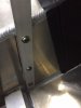
I am so glad you guys are on this forum. Being a novice, I was guessing, and guessed wrong. I will get backing plates and get the mounting angle corrected. Any other suggestions?

- Forums
- GT40 Replica Manufacturers' Corner
- RCR Forum - RCR40/SLC/917/Superlite Aero
- The SLC Clubhouse
You are using an out of date browser. It may not display this or other websites correctly.
You should upgrade or use an alternative browser.
You should upgrade or use an alternative browser.
Mark's GT-R Build
- Thread starter mksetter
- Start date
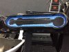
I am preparing to put the fuel tank in the center tunnel, but learning from Dean, I wanted to make sure I had all of the holes drilled in the tunnel that I could ever use before the gas tank gets installed. With that in mind, I wanted to add a vertical component to the console that can house the stereo and any electronics. At this point, I just made the support brackets, attaching them to the center console and the dash support. Later I will add the face plate and decide on what goes where.
Attachments
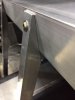
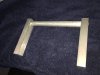
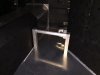
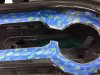
I am planning to take this car on the Hot Rod Power Tour, and that means by brother-in-law and I will be driving a few thousand miles in this car. The passenger foot well is really deep, and so to make the ride a little more comfortable for the passenger, I made a foot rest. It may look a little tall in these photos, but I will be adding Luxury Liner Pro, from Second Skin Audio, along with the tub, and carpeting, so I am figuring an inch will be used in these materials. I don't know what finish to put on this, given that shoes will be resting on it. Any suggestions on materials?
Attachments

Frank Clark
Supporter
I don't know what finish to put on this, given that shoes will be resting on it. Any suggestions on materials?
I personally would try bed-liner.
Great Idea! Thanks!
I am planning to take this car on the Hot Rod Power Tour, and that means by brother-in-law and I will be driving a few thousand miles in this car. The passenger foot well is really deep, and so to make the ride a little more comfortable for the passenger, I made a foot rest. It may look a little tall in these photos, but I will be adding Luxury Liner Pro, from Second Skin Audio, along with the tub, and carpeting, so I am figuring an inch will be used in these materials. I don't know what finish to put on this, given that shoes will be resting on it. Any suggestions on materials?
Make the tube out of stainless, then brush it with sand paper. If it gets lots of scratches, just rebrush it with sandpaper. Easy to maintain.
That would go well with the look I am after. Need to get some stainless.
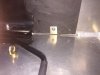
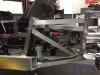
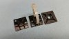
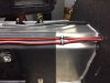
I got the backing plate material for the five point harness and got the shoulder straps re-installed, with about a 20 degree drop and closer to neck width apart from each other. Thanks for keeping an eye on this build. I am going to include the seat belts and the seat mounting bolts in the backing plate under the floor.
Attachments

I received a gift from RCR. They are the short brake lines for attaching the valves to the front and rear brake lines. For us novices, this made finishing the brake lines safely a reality. I don't mind making a mistake, like the seat belt mounting, because those following the forum can see it and point it out. Making a mistake on fabricating a brake line most likely would not be noticed and could be serious. Thanks Fran, Kristin and the RCR Crew.
As I put the vertical supports in the console, I also drilled and tapped the tunnel for getting electrical connections from the front of the cockpit to the engine area (More on that later). I wanted to get all of the holes drilled and tapped in the console that I could possibly use before I put in the gas tank.
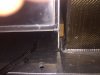
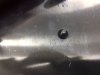
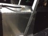
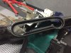
When installing the gas tank, I followed Dean's suggestion of using a strip of wood as a spacer between the gas tank and the inside wall of the tunnel. I could only get one side to fit, but it will hold the tank from shifting. I used rivnuts identical to Dean's method. Worked great. Thanks Dean.
When installing the gas tank, I followed Dean's suggestion of using a strip of wood as a spacer between the gas tank and the inside wall of the tunnel. I could only get one side to fit, but it will hold the tank from shifting. I used rivnuts identical to Dean's method. Worked great. Thanks Dean.
Attachments
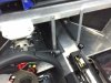
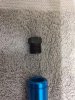
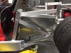
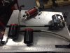
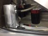
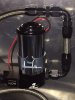
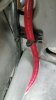
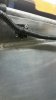
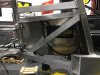
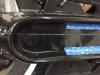
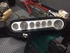
With the fuel tank in to stay, I can finally get to work on the fuel delivery system. The lateral heat shields that I used not only will keep the heat from the engine confined, but I two great surfaces to mount accessory components. I wanted to limit the vibration noises that might come from the fuel pumps, so I mounted them with rubber washers. I also wanted the canister fuel filters to be easily accessible from under the car. I used all Aeromotive pumps and filters, with Earl's AN fittings.
I have a few more lines to make, like from the regulator back to the swirl tank, and I have to clamp the fuels lines where ever possible, but the layout worked great! I don't know how you guys do this in the SLC beside the fuel tank, in that very limited space. You have more talent than I have.
I have a few more lines to make, like from the regulator back to the swirl tank, and I have to clamp the fuels lines where ever possible, but the layout worked great! I don't know how you guys do this in the SLC beside the fuel tank, in that very limited space. You have more talent than I have.
Attachments
-
 IMG_3262.JPG70.3 KB · Views: 546
 -
 IMG_3410.JPG74.4 KB · Views: 509
 -
 IMG_3409.JPG40.8 KB · Views: 477
 -
 IMG_3412.JPG72.8 KB · Views: 499
 -
 IMG_3414.JPG72.9 KB · Views: 545
 -
 IMG_3418.JPG66.7 KB · Views: 449
 -
 IMG_3420.JPG68.3 KB · Views: 472
 -
 IMG_3422.JPG71 KB · Views: 535
 -
 IMG_3421.jpg74.9 KB · Views: 509
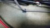
Mark, I am car rookie. Flying things have been my life and I wonder if we should worry about the fuel line at the bottom of the swirl pot outside of the chassis rail?
Mike
Mike
Dr. David
Lifetime Supporter
Hi Mark, Great progress and craftsmanship on your build!
Stabilizing lines with zip-tie pads:
One method of stabilizing your lines is with zip-tie pads. I first used this method when I wanted additional stability of the tail light electrical line conduits on the rear clip of My Ultima GTR, with external visible bodywork on the other side of the panel. Also, I don't like to drill holes in some structural things because I think it weakens them. I buy zip tie pads from Home Depot or Lowes and remove their sticky pad with paint thinner (I don't trust the adhesive). I then glue it onto the cleaned roughened panel with JB Weld, using a white zip tie as a handle for positioning, and to make sure the glue doesn't enter the slot needed for the permanent zip tie. If you have what you perceive is a high-stress line, with nothing important on the other side of the panel, you can also rivet them with 1/8" rivets, but I have never had a glued one come loose.........In my shop, white zip ties are used frequently, but are for temporary only, (Harbor Freight) and all black zip ties, no matter what size, all have stainless steel tabs in them, (Speedway Motors, Ty-Wraps, etc.).
Just one more way to do it,
Looks like you are having a good time with a very nice build!
David
Attachments
I appreciate the feedback.
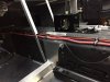
I looked at Allen's GTR and his entire fuel system is outside the frame rails, so that makes me feel more secure in my set-up. I looked at the option of getting the output line from the swirl tank inside the angular frame rail, but there is no room. I still hear what you are suggesting in that there is a higher margin of safety if I can get inside the frame. With that in mind, I can mount the fuel line on the inner aspect of the horizontal frame rail (it is not clamped down yet). That will protect the fuel line almost as much as if it was completely inside the frame.
I love the idea of not drilling into supporting frame rails, so the idea of using zip-tie pads is awesome! I will pick some up. I am holding of on doing the final line tie-down until any comments have been made.
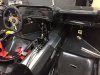
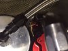
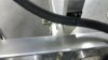
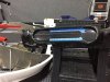
Before I installed the fuel tank, I drilled and tapped for some electrical lines to be run along the console. The tunnel under the fuel tank will not hold much beyond the coolant lines, the brake lines, the heater hoses and the steam lines to and from the radiator. With that in mind, I ran the 1ga. positive battery cable and an 8 ga. set of power lines along the console. The heater hose control valve is just temporarily mounted on a screw that was already in place on the firewall to hold the backing plates in place, but I wanted to run the valve control line up to the console verticals that I put in place. I plan to run the independent power supply required by the Holley Dominator II computer along the passenger side of the console. The 8ga. power line is for the option of a power amp for the sound system, if it is worth putting one in. I will hold off on that decision until I hear the sound levels produced by the motor just a few inches from the cockpit.
Attachments
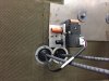
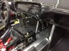
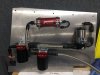
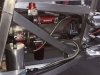
I mounted the Holley Dominator engine control module on the passenger side lateral heat shield. This system is the only one available that will run duel throttle bodies, and it looks awesome! The wiring harness is completely labeled and even has the heat shielding in areas where it is likely needed. The power supply harness is wrapped in braided nylon and is long enough to run from the rear mounting position to the front mounted battery. Saves me having to make a custom harness.
Attachments
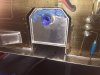
I saw how awesome Dean's dash looked with the gauges mounted, so I decided to start on the dash board. I outlined the gauges, then connected the holes needed for each gauge, knowing that a wiring harness will be used behind the gauges, so separate holes for each gauge is not an option. The finish line was hard to see using a black Sharpie pen, so I taped it off. I tried to keep as much fiberglass backing as I could for strength. I rough cut with a separating disk on a Dremel, then started sanding back to the finish line. Not quite done yet.
By the way, the gauges look fantastic. Super quality by Speedhut. Thanks Fran.
By the way, the gauges look fantastic. Super quality by Speedhut. Thanks Fran.
Attachments
I finished trimming the dash board gauge cutout, then mounted the gauges. They are fine!
I would like to anodize the gauge surround in red, to reduce the glare and add some color to the interior. Can I do that with this material? Does it already have a finish on it? Any comments?
I tried to work on the brake line valves and brake line switches, but ran into some problems. Need to order different valves. I could not get the brake line to seat on the 3/8 side. I will pick that up next week.
Attachments
Similar threads
- Replies
- 3
- Views
- 2K
- Replies
- 9
- Views
- 809
- Replies
- 5
- Views
- 941
- Replies
- 63
- Views
- 6K