Mark's GT-R Build

Thanks for the suggestion Ken. They have amazing fabrication capability. I may be able to get some ideas, but certainly like seeing what a finished car looks like.
 
Cool build thread Mark. Stopped by H's shop yesterday and saw his GT-R build on my way back from missing Fran and the new Superlite Aero at Road ATL. The fab work on H's GT-R is unbelievable. He's done some incredibly brilliant things to his build and I was floored at his eye for design and just plain love/passion for bespoke fabrication.
 
After I got the fuel delivery system all mounted, I removed the lateral heat shield, removed all of the mounted hardware and wanted to put an finish to the metal surface that was available. I used Ballistol and medium steel wool to get a satin finish. The middle picture shows half of the surface prepped. The finished product looks much better.
 

Attachments

  • IMG_3448.JPG
    IMG_3448.JPG
    47.1 KB · Views: 482
  • IMG_3450.JPG
    IMG_3450.JPG
    74 KB · Views: 388
  • IMG_3455.JPG
    IMG_3455.JPG
    76.5 KB · Views: 420
Since I am probably mounting the lateral heat shields for the long term, I can start adding the "inside" features. I am running a modified LS3, but want to have remote mounting of the coils to look less like an LS motor, so I am mounting them on the forward lower aspect of the inside of the heat shield. They will be about nine inches from the exhaust system and I plan to have air deflectors under the car to get air into the area. Here you can see the coil rack provided by Katech, mounted prior to the heat insulation being applied (middle picture), then after the Second Skin heat barrier.
 

Attachments

  • IMG_3452.JPG
    IMG_3452.JPG
    76.7 KB · Views: 345
  • IMG_3447.JPG
    IMG_3447.JPG
    71.4 KB · Views: 382
  • IMG_3453.JPG
    IMG_3453.JPG
    64.1 KB · Views: 371
Based on the awesome recommendations of this forum, I utilized steel backing plates for the five point harness. I wanted them to match the look of the firewall, so I covered them in Lava Shield. I also used Lava Shield over the Second Skin heat barrier on the inside of the lateral heat shields to maximize heat containment. Just a few more details to do in the engine area and I can put the motor back in.
 

Attachments

  • IMG_3457.JPG
    IMG_3457.JPG
    93.7 KB · Views: 378
  • IMG_3458.JPG
    IMG_3458.JPG
    95.8 KB · Views: 368
  • IMG_3461.JPG
    IMG_3461.JPG
    91.4 KB · Views: 397
The appearance of the engine area is very important to me in this build. One of the areas that has bothered me is the adhesion of the Lava Shield in one area of the firewall. I have attempted to get better adhesion with a heat gun and have re-seated the Lava Shield a number of times.

To solve the problem, I decided to make a trim piece that would screw in place a dress this area properly. An aluminum strip, cut to fit, polished and screwed in place solved the problem.

Almost ready for the motor.
 

Attachments

  • IMG_3463.JPG
    IMG_3463.JPG
    105 KB · Views: 350
  • IMG_3464.JPG
    IMG_3464.JPG
    138.2 KB · Views: 331
  • IMG_3470.JPG
    IMG_3470.JPG
    86.2 KB · Views: 354
  • IMG_3471.JPG
    IMG_3471.JPG
    97.2 KB · Views: 373
  • IMG_3474.JPG
    IMG_3474.JPG
    73.2 KB · Views: 368
Another area requiring some dress-up is the edge of the lateral heat shield, where the Second Skin Heat Shielding and the Lava Shield layers show.

Using 1" X 1" aluminum angle, I cut to shape, trimmed, polished with steel wool and screwed in place trim pieces on each side that make these areas look finished.

Next I am headed to the front area to get the brake lines finished.
 

Attachments

  • IMG_3465.JPG
    IMG_3465.JPG
    78.1 KB · Views: 416
  • IMG_3466.JPG
    IMG_3466.JPG
    66.9 KB · Views: 360
  • IMG_3467.JPG
    IMG_3467.JPG
    82 KB · Views: 364
  • IMG_3468.JPG
    IMG_3468.JPG
    71.9 KB · Views: 349
  • IMG_3473.JPG
    IMG_3473.JPG
    78.6 KB · Views: 482
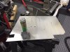
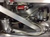
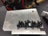
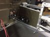
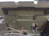
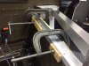
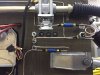
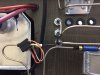
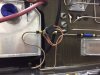
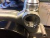
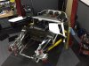
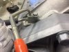
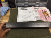
The GT-R was shipped with some perfectly bent stainless brake lines, including the shorter lines that go from the foot box wall to the tunnel, but unfortunately they did not have provision for the front and rear residual pressure valves or the pressure indicator switches for the brake lights or the clutch. Kristin and Josh at RCR tried to solve the problem by sending me some lines that would allow for the residual pressure valves that came with the car to be installed, but me being the novice, I could not get those valves to work. The additional lines also did not have provision for the pressure switches.

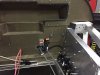
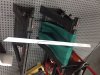
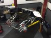
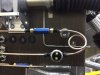
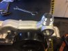
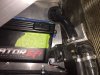
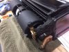
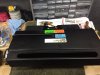
I think I might get the ugly brake line award, but rather than try to flare my own custom brake lines, I chose to use pre-made copper nickel lines that come flared. The only problem is that they come in 12 inch lengths.

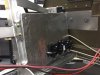
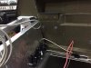
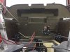
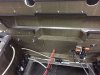
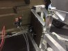
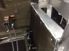
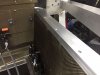
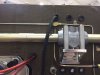
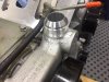
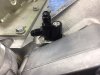
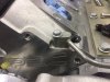
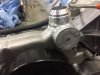
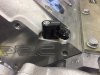
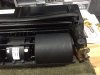
That being the case, I designed the brake lines using only 12 inch lines, thus the odd looking system. Not being able to get the provided valves to work, I got some novice approved Wilwood valves that worked great. I had to make a support bracket for the helix end, but it has no vibration at all.

Some parts of the build you are proud of. Other parts simply get the job done.
 

Attachments

  • IMG_3475.JPG
    IMG_3475.JPG
    81.6 KB · Views: 362
  • IMG_3476.JPG
    IMG_3476.JPG
    78.3 KB · Views: 406
  • IMG_3477.JPG
    IMG_3477.JPG
    88 KB · Views: 327
  • IMG_3478.JPG
    IMG_3478.JPG
    81.7 KB · Views: 342
  • IMG_3479.JPG
    IMG_3479.JPG
    74.3 KB · Views: 310
  • IMG_3480.JPG
    IMG_3480.JPG
    83.1 KB · Views: 357
The chassis is almost ready to get the motor put in, so I am getting the motor modifications done. The way I want it to look requires some help from the guys at Mannix Automotive, next door to my shop. We decided to use -20AN fittings for the output side of the water pump, milling an access, then using the original hole for a thermostat. The photo shows the milling results, with a nice clean opening that looks to ideal for flow. The -20AN fitting fits perfectly. Now ready for welding. We plan to use the same size -20AN fitting on one of the stainless coolant tubes. The return side is not really visible, so we plan to use flex tubing, along the lines of that used in Allan's GTR build.

A plate will be welded to close off the original output hole, the it will be drilled and tapped for a thermostat sending unit. We are going to hold off on the modification for the return to the water pump until the motor is in the car, so we can make sure we have it right.
 

Attachments

  • IMG_3496.JPG
    IMG_3496.JPG
    79 KB · Views: 308
  • IMG_3497.JPG
    IMG_3497.JPG
    66.2 KB · Views: 304
  • IMG_3498.jpg
    IMG_3498.jpg
    73.2 KB · Views: 278
  • IMG_3500.JPG
    IMG_3500.JPG
    59.4 KB · Views: 273
  • IMG_3499.JPG
    IMG_3499.JPG
    61.5 KB · Views: 360
Completing some steps seem to take a lot of work, yet you don't really feel you got that much done, such as the brake lines. Other steps don't really take much work, but you really feel a milestone has been accomplished. That is the case with mounting the front end. It took a lot to get to this point, having the tunnel contents either in the tunnel or completely mocked up so there are no surprises. It was a little tricky doing this single handed, but it went in place just like it should.

Now comes designing the layout for the contents of the front end - the battery, the lift pump, the coolant lines, the AC dryer and associated parts, all keeping in mind the front hood "nostrils" will take up some space.

This is the perfect hobby. Working with your hands and your mind.
 

Attachments

  • IMG_3502.JPG
    IMG_3502.JPG
    72.9 KB · Views: 503
  • IMG_3503.JPG
    IMG_3503.JPG
    68.9 KB · Views: 396
  • IMG_3504.JPG
    IMG_3504.JPG
    88 KB · Views: 435
This is the perfect hobby. Working with your hands and your mind.

Yup, anybody can tighten a bolt down. Takes an entirely different person to design the parts being bolted together.
It certainly becomes addicting.


Looking good!
 
Scott, you have taken this hobby to an entirely different level. Your car is AMAZING!!!! From the air intake to the body work, I stand back in awe of your knowledge and skill. Thank you for your contribution to each of our builds.
 
Scott, you have taken this hobby to an entirely different level. Your car is AMAZING!!!! From the air intake to the body work, I stand back in awe of your knowledge and skill. Thank you for your contribution to each of our builds.

Thanks for the compliments Mark. I have yet to decide if it is a curse, or blessing. I have to do it to keep my mind busy personally, not a choice really. That, and the "if you don't have time to do it right, how will you have time to do it over" mentality.
Youtube wasn't around 29 years ago when I started working on my 67 Camaro at 15 yo, nor parts selection. Remember when you could only get decent parts from local parts stores or mail order from a magazine? Really limited what you could do. Now, with the internet, it has exploded with small parts manufacturers and a huge selection of assembly parts with easy access to find. Great time to be a car guy!
 
I got the water pump back after the -20AN fitting was welded into place. The old water pump outlet was closed with a flat plate, then drilled to serve as the new coolant temperature sensor location. The welding looks great.

I am also changing the GM steam tubes over to -4AN braided lines, so I started that conversion. I am waiting on accessory drive belts, then can put the engine together and get tit installed.
 

Attachments

  • IMG_3505.JPG
    IMG_3505.JPG
    75.5 KB · Views: 246
  • IMG_3506.JPG
    IMG_3506.JPG
    67.9 KB · Views: 235
  • IMG_3507.JPG
    IMG_3507.JPG
    66 KB · Views: 236
  • IMG_3508.JPG
    IMG_3508.JPG
    77.3 KB · Views: 270
  • IMG_3509.JPG
    IMG_3509.JPG
    60.9 KB · Views: 257
  • IMG_3510.JPG
    IMG_3510.JPG
    77.6 KB · Views: 279
Before putting the engine in place, I wanted to get everything possible completed in the firewall area and the area between the lateral heat shields, so the heater control valve that I got from Chevs of the Forties needed to get installed. The size of my Cross Ram Air Intake basically makes mounting anything on the firewall between the heat shields not an option. The passenger side lateral area seemed to work well.

I am awaiting the "T" for the 5/8 heater hose line, then will finish this.
 

Attachments

  • IMG_3513.JPG
    IMG_3513.JPG
    77.3 KB · Views: 227
  • IMG_3514.JPG
    IMG_3514.JPG
    87.2 KB · Views: 295
Keeping with the theme to have many things going at once, I decided to start on the air conditioning system. The first item is rotating the coolant line fixture as illustrated in the build manual. Going slow and careful is the key so as not to damage the copper line attached to the fixture needing rotation.

As you can see in the photos, the heater hose attachments are directed outward towards the passenger wheel well, so I had to mount the AC unit slightly towards the middle to make room for the heater hoses.

To increase air flow, I connected the holes from the factory to make one continuous opening. The AC unit was narrower than the spread of the holes, so the hole from the factory most to the passenger side will not be used.

After cutting the slot and mounting the AC unit, I marked the opening and cut out the slot in the AC unit. This is easy.
 

Attachments

  • IMG_3515.JPG
    IMG_3515.JPG
    83.4 KB · Views: 292
  • IMG_3516.JPG
    IMG_3516.JPG
    79.1 KB · Views: 285
  • IMG_3526.JPG
    IMG_3526.JPG
    52.2 KB · Views: 252
  • IMG_3527.JPG
    IMG_3527.JPG
    93.2 KB · Views: 278
  • IMG_3529.JPG
    IMG_3529.JPG
    74.3 KB · Views: 281
Back
Top