Mark I agree with Jared the roads in Pa suck so there will be repairs from time to time and yes this will be the first mod among many once my car arrives the end of Aug per Fran keep your fingers crossed Jared needs a crushing partner

- Forums
- GT40 Replica Manufacturers' Corner
- RCR Forum - RCR40/SLC/917/Superlite Aero
- The SLC Clubhouse
You are using an out of date browser. It may not display this or other websites correctly.
You should upgrade or use an alternative browser.
You should upgrade or use an alternative browser.
Mark's GT-R Build
- Thread starter mksetter
- Start date
Mark can you send me the order numbers on the Raptor Steering Wheel and Quick release you used for your car it's the same one I would like to use.
Larry
Larry
Hi Larry:
My steering wheel is a Momo Eagle with leather wrap. They are available at many outlets. I love the steering wheel on my Ferrari 458 and I chose this Momo Eagle because of the molded hand positions and it is the closest wheel I could find to the Ferrari steering wheel.
As for the quick release hub, I would refer you to the locations on the forum I got my information. First is the build wiki. It has a whole section on steering wheels and adapters. Also, there is a thread in the SLC Clubhouse on NRG quick release hub part numbers, dated 12/29/16. It is worth a look.
I have an Olds steering column, so my NRG adapter is SRK 170H. I stated in the thread above that I could not get it to fit, but I was later able to get it all to work.
Finally, I added the Summit Raptor Pro wireless switching system to the steering wheel. It is a bit pricey, but really cool and saves you on ordering other switches you will need in the cockpit.
Hope this helps.
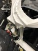
I am finally back in the shop doing some building! Today it is time to attack the door seals. Superlite cars used for track only may not need to pay attention to this, but street cars need to have weather stripping and as much of an air tight cockpit as possible.
The GT-R has a great area for weather stripping in the spider, along the "A" pillar. around the top of the door and along the back of the door. The front edge of the door has no seal, and the seal along the rocker panel is present, but less than what I want. There is a wide open area for air and water to enter the cockpit. Also, the area in front of the door when the door is open is UGLY.
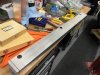
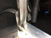
To get started, I had to create a smooth surface for 1" x 2" aluminum rectangular tubing to make up the front edge of the new door seal. The welding bead rising up from the adjacent surface would limit the seating of the tubing.
A 1" x 2" rectangular tube was cut to fit, then had to have a finish put on the surface.
The GT-R has a great area for weather stripping in the spider, along the "A" pillar. around the top of the door and along the back of the door. The front edge of the door has no seal, and the seal along the rocker panel is present, but less than what I want. There is a wide open area for air and water to enter the cockpit. Also, the area in front of the door when the door is open is UGLY.
To get started, I had to create a smooth surface for 1" x 2" aluminum rectangular tubing to make up the front edge of the new door seal. The welding bead rising up from the adjacent surface would limit the seating of the tubing.
A 1" x 2" rectangular tube was cut to fit, then had to have a finish put on the surface.
Attachments
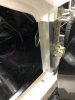
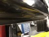
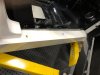
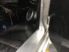
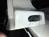
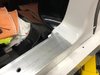
With this piece in place, I now have the forward surface available for weather seal. It also really cleaned up the appearance of the area. With the door closed, the new piece has a really nice fit relative to the front of the door, with enough room for weather stripping. From the other side you can see how much space was filled with this piece.
Although this has improved the surface available for weather stripping, adding an angle piece will greatly improve the seal.
Although this has improved the surface available for weather stripping, adding an angle piece will greatly improve the seal.
Attachments
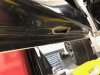
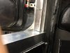
Using angle stock cut to fit, I was able to line up with the "A" pillar and the rocker panel.
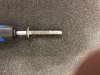
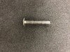
I needed to use 1.5" screws to mount all of this, and sometimes I had some difficulty getting the screws to line up with the threaded holes, given the depth of the stock I was going through. I could either enlarge the holes, which can make for loose pieces later, or I could taper the ends of the screws.
I elected the second choice. I used a grinder to taper the ends of the screws, then re-tapped the threads.
Without the tapered screws, I could not, for the life of me, get this last screw to grab threads. The tapered screws went right in.
With the angled stock in place, it looks good and has great surfaces for weather stripping.
I did the same thing on the other side. A future time I will develop the door seal along the under side of the door.
Attachments
While I was on the Power Tour, I had the chance to talk to a lot of car builders about wiring a custom car. Although the cars are different and the details are different, most builders used Ron Francis Wiring or Painless Wiring components. I am sure the Infinity System is a great choice and provides options that may not be available with some of these other wiring systems. My problem is that I don't understand the system and I am having trouble making it look neat and organized, like I want it.
I saw the wiring H did and I was blown away!!! I may not be able to get it as good as he has it, but I want to get it better than I have it.
Also, I anticipate that I may have problems trouble shooting the Infinity System should a problem arise. I kind of view the system as having VooDoo boxes that perform the magic.
Again, I know Fran uses the best components he can find and the Infinity System certainly can make it easier to build. All that being said...….
I have decided to remove the Infinity System and re-wire the car using Ron Francis Wiring Components. They were exhibiting at the Power Tour so I had a chance to speak with their knowledgeable staff and got the stuff ordered. Should be here soon, then I will attack the wiring system again.
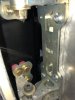
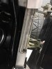
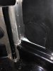
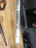
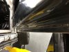
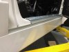
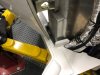
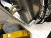
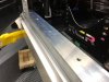
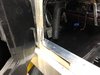
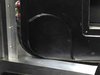
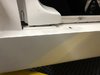
I am now wanting to finish the remaining areas needing a door seal, namely the door sill area. The underside for the door comes with a bulge right where one level of the door seal needs to go so I removed that section and will re-fiberglass that area later. The door has two levels that have surfaces ideal for adding weather seals, so I intend to make two levels in the door sill. The interior tub comes with a vertical area that could be used for one of the door seals, but the height of the tub "Lip" is less than ideal in providing a good seal and I think the esthetics can be improved.
Attachments
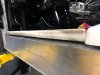
To make the area look like it has a door sill and to make the primary seal. I used a 2" x 3" rectangular aluminum tube. Because the body work has screw heads protruding above the plane of the body work in the area, I had to drill holes to serve as a recess for the screw heads. I also had to remove the interior tub lip down to the level of the body work to allow for the positioning of the aluminum. There is a complex curve in the rear area of the door sill body work that I had to "trial and error" the fit of the aluminum until it would seat, then will add edge trim to the rear edge of the aluminum sill to fill in the small remaining gap. This sill now matches the step in the underside of the door perfectly.
Attachments
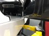
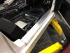
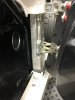
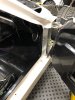
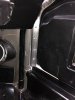
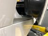
A second door seal can be made using the very lower inside edge of the door. This step in the underside of the door is 1 inch high, so I added 1" x 1" angle aluminum from the area just behind the wheel well to the rear of the door opening. The body has a rather large gap between the door and the rocker panel that would be very difficult to seal off without this second 1" piece added. There was also am ugly gap in the fiberglass that I was able to cover with this aluminum. At the time of final assembly, there will be two excellent areas for weather stripping to be added to the door. Ideally there will be two to three levels of weather seal all the way around the door.
Next I have to put a finish on these pieces and mount them, then add a flange to the lower front edge of the door to square off the curved area of the door to match the right angle of the door sill.
Next I have to put a finish on these pieces and mount them, then add a flange to the lower front edge of the door to square off the curved area of the door to match the right angle of the door sill.
Attachments
Getting there Mark, looking good.
I picked up a few sets of tail hinges yesterday from the water jet shop, so when you're ready.
I picked up a few sets of tail hinges yesterday from the water jet shop, so when you're ready.
Hey H:
I am glad to be back building the car. I am ready for the hinges any time. I am working on body alignment as I set up the door sills because the rocker panel needs to be in position to locate the sill. Also, I don't know where things are with the interior door panels you were working with, but if any are available, count me in.
The tail lights you made are gorgeous and I am working on getting the fog light buckets mounted. I have not started the wheel well liners because I want the hinges in place before I start those.
Let me know if you have any other "goodies" that I can add.
Thanks for all of your help and inspiration. You have really helped make the GT-R special.
Mark
Door cards are getting close now, so within the month they should be available i'd think.
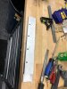
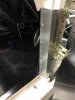
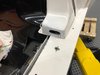
The next job is to create a complex curved sheet metal piece to allow for a door seal in the lower front area of the door, which is curved and on two different planes between the vertical area and the lower horizontal area. I made a cardboard template to match the curvature of the lower front corner of the door, then taped it in place to see how it needed to adapt to the different planes. You can see in the last photo how the cardboard fills the inside of the door seal with the door almost closed.
Attachments
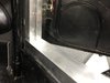
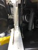
I then transferred the template to sheet metal, mounted it to the door sill and adapted it to the curvature needed to match the door. I will rivet the upper end of the sheet metal in place and caulk it at the time of final assembly.
Attachments
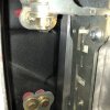
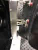
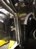
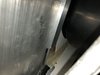
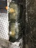
With the door sill in place, I have an opportunity to gain access to some hidden bolts that need nuts attached and tightened at final assembly. You might recall that I fiber glassed the bolts at the lower end of the rear door frame because there is no access to the bolts or the nuts in this area. Glassing the bolts worked great, but I still had to get the nuts on them. With the aluminum door sill in place, it hides the access opening I cut in the area. You can see the end of the bolt needing a nut thru the opening. This should really help in final assembly.
Attachments
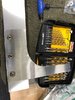
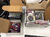
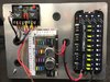
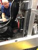
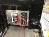
As I mentioned before, I am removing the Infinity System and wiring the car using Ron Francis components. I ordered the following from Ron Francis: 1: the XP66 Express Wiring System, 2: the AR 99 Ice Box Dual Fan Controller, 3: the BX 10 Relay System and 4: the MS44 Battery Disconnect. The express wiring system allows you to make your own wiring harness, with associated fuses and some relays. I wanted to program additional relays, so I added the BX 10, which is optional. The MS44 is a FOB controlled battery shut off, that can also handle the remote control of other accessories.
Attachments
After seeing H's wiring in his build, I was no longer going to be satisfied with anything other than organized wiring. His wiring is amazing. There are a variety of locations the components can be mounted. I wanted easy access for wiring and some room that will allow me to keep things very neat and organized. With that in mind, I chose the use a mounting plate behind the driver seat. I have the seat angled significantly so there was a lot of room in the area. I have just started the wiring, but some of the connections are in place. I put "legs" on the mounting panel to allow me room to run wires behind the mounting panel and thru the firewall and to bring the mounting plate out to the level of the interior tub. The legs are 2". I have to refine the trimming of the tub, but it is going to be covered in carpeting, leaving a cut out so the electronics can be seen. Should look good.
Attachments
I like it. I was thinking something similar with the tub. Nice work!
Very clean looking! I’m wishing I had gone down that path as well. When I pulled the infinity system the PKE system I was running had a surprising amount of relays and fuses already built in so we were thinking it would be relatively minor to just scratch build one - then I started adding more and more stuff ... and my electronics overgrew the original panel we made. A system like this integrates everything into a more compact package and creates a much cleaner look. Hindsight is 50/50 and I don’t have your discipline for going back so I’m moving forward - but looking at your pics with some jealousy. ")
Similar threads
- Replies
- 3
- Views
- 2K
- Replies
- 9
- Views
- 809
- Replies
- 5
- Views
- 941
- Replies
- 63
- Views
- 6K