Mitch Krause's RCR GT40 Build

Markus

SPRF40
Lifetime Supporter
I think I have the shifter and shifter cables done and sorted out.

The shifter in the cabin has a throw that is from 1 inch to 7.5 inches from the dash without any of the cables connected. After much setting of the various adjustments on the cables, I have it to where first (and any gear with forward throw) gear is 2” from the dash, neutral is 4” from the dash and second is 6” from the dash. That seems to be about centered and leaves an inch or 1.5 inches on each side if I have to adjust.

The shifter has a side to side thrown of about 14 degrees (relative to the shifter support box) from vertical both left and right. Right now, it is in reverse at 13.5 degrees to the right, first at about 10 degrees to the right and third at about 3 degrees to the right. This is obviously biased towards the right, I had fooled around a little bit and ended up liking the rightward bias a little bit, as it goes into reverse easily (the most right), and leaves me some room to find 5th (I haven’t found that yet).

With an inclinometer on the end of the transmission, and zeroed at neutral. The transmission shaft rotates about 7 degrees counter clockwise to get into reverse and about the same clockwise to get into the higher gears.

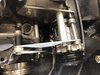
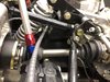
As far as securing the shifting cables, each one is secured at three points. The first picture shows the front securing of both cables, onto the square tube behind the cabin, basically just aft of where the cables come out of the firewall.

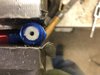
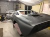
The second picture is the mid securing point for the big cable. Low on the frame at the front of the engine.

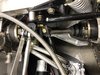
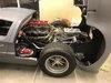
The third picture is the mid securing point for the rotational cable. On top of the frame about at the back of the engine.

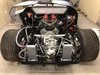
The fourth picture shows the back securing point for both cables (with help of little red arrows). I put a couple of braces in that do a few things. They firm up the engine oil cooler, provide mounts for the transmission oil distribution and provide points at which to secure both shift cables.

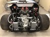
Last picture is everything hooked up at the rear of the transmission.


Hi Mitch,

I just went through the pics regarding your shift cable routing in post #295..... based on past experience some bent radius' seem very tight to me.

Have you tried to move the shifter with the cables connected to it? Or just move the cables by themself?

Markus
 

Mitch Krause

Supporter
This has been a week long endeavor. Had some interference between ac lines off the compressor and the radiator hose off the water pump housing. So had to redesign and fabricate new brackets. Needed to move the ac 7/8 rearward to give full range of adjust and line up front ac pulley with engine pulley. Move the ac up an inch, and the make a new adjust bracket. Trim the flange on the ac about 3/8 to get alignment and lots of fooling around. Four different tries at the adjust bracket until I had it spot on. All is well now but this was lots of cutting, figuring and grinding. Two trips to the store until I could get the right size belt that was nearly tight at front of adjust. 36 and 5/8 belt length.
 

Attachments

  • 3FADB0A0-E996-46AC-8F63-2DE36EED9166.jpeg
    3FADB0A0-E996-46AC-8F63-2DE36EED9166.jpeg
    404 KB · Views: 802

Mitch Krause

Supporter
Hi Mitch,

I just went through the pics regarding your shift cable routing in post #295..... based on past experience some bent radius' seem very tight to me.

Have you tried to move the shifter with the cables connected to it? Or just move the cables by themself?

Markus

Markus,

Thanks for the note, I was concerned with the same thing, but that was the only way to get the cables routed so that the cleared everything else (ac pump and headers). It seems to work, I have everything attached to the shifter and it shifts pretty easily and fluidly, so fingers crossed that continues to be the case when it gets some real use. The only other real option I could see was to route them very low to start so that they went below the belts, but then the problem was that there was no attach points. There was a little less initial bend radius that way, but then more bends as you had to come back up and around the motor mounts and oil filter.
 

Mitch Krause

Supporter
My solution to getting spray nozzles in the transmission connectors. The holes in the aluminum connectors were just slightly smaller than 5/16 inch. So drill out to 5/16. Tap them to 3/8 by 16 thread size. Turn in a nylon bolt (3/4 inch long hex head) about 1/2 deep which is where my threads end. Put red loctite on the threads before turning in the bolt. Cut the bolt off flush with the end of the connector. Center punch it. Drill 1/8 inch hole through bolt and walla you have a 1/8 inch spray nozzle.
 

Attachments

  • EFB25505-650C-4302-8E0D-9E53D3C6887C.jpeg
    EFB25505-650C-4302-8E0D-9E53D3C6887C.jpeg
    212.3 KB · Views: 862

Mitch Krause

Supporter
Just so I can attach one more picture. Most recent has been getting the clutch installed and then getting the oiling systems, coolers and everything else back in place. Biggest pain was a few days of in and out with the dogbone as I had to grind some on the transaxle ridges, some on the competition cover and mostly on the dogbone to get the clearance so it went in place. But everything working out nicely and I think this is the last time this stuff goes in. As per the previous post, I am doing the last little bit on the transaxle oiling system (the nozzles as they are).
 

Attachments

  • 3EDD2DC1-7F2E-47F1-8838-F3D869C1859D.jpeg
    3EDD2DC1-7F2E-47F1-8838-F3D869C1859D.jpeg
    521.2 KB · Views: 820

Mitch Krause

Supporter
One slight change on the oil nozzles. Had not quite finished when I posted before. Decided to use oil resistant black RTV on thread instead of loctite. Can’t quite figure out if loctite is ok for nylon or not.
 

Randy V

Moderator-Admin
Staff member
Admin
Lifetime Supporter
One slight change on the oil nozzles. Had not quite finished when I posted before. Decided to use oil resistant black RTV on thread instead of loctite. Can’t quite figure out if loctite is ok for nylon or not.
Why use any compound at all. It sounds like the nylon is trapped in there pretty good... If you really want to use something on it, I would use Right-Stuff...
 

Mitch Krause

Supporter
Lessons Learned in Bundles of Snake Charming.

So you test fit your headers a few different times over the many past months when working out clearances and lines and everything. Each time you bolt them up snug with an appropriate bolt and everything goes fine. Then you are ready to install for the “last” time.

So you clean everything up, put on the RTV so that is skins over, carefully interlace the headers and put them in place, snugging them up with the “right” final bolts in the same furthest forward and aft bolts that you used when test fitting. Now to proceed with the rest of the bolts.

Thus enters lesson 1 – Should have tried all the bolts. There are three different bolts of the “right” length that you can’t now get into their holes. There is not sufficient clearance from the header pipe to get the 1.25 inch bolts into the hole without bending the header pipe. That is impossible with the headers mounted and probably impossible with the headers off. There are three bolts that this affected, the second from the front on each side and one additional one on the left side.

Lesson 2 – You can’t snug up a couple bolts all the way and get the rest of the bolts in either. You have to just barely start a few of the bolts and “walk” the header in by tightening each bolt a turn or two at a time so that you can get the bolts in the hole straight.

Now it is bed time, so you leave things for tomorrow with half cured RTV and one header on and one off.

Lesson 3 – The next day, scraping all the RTV off the heads and the headers will ruin at least three fingernails of a perfectly good manicure. Two thumbs and one forefinger. But it all got off.

Lesson 4 was the next day and was the discovery that if I ever want to change spark plugs, I am going to have to remove the headers. The flanges cover enough of the access to the spark plug that it doesn’t look like even the thinnest walled socket head will be able to turn them out with the headers installed.

How do you solve the problem of the three bolts that you can’t get in the hole? In my case, the “right” length bolt is 1.25 inches with a star washer. Depth in the head is 0.75 inches, header flange is 0.5 inches. One of the holes (not second back from the front on either side) could have the 1.25 inch bolt turned somewhat hard through the flange hole and get through the hole. The threads on the very end of the bolt were somewhat scarred by the action, but since 0.75 inches now protrude past the flange, you can run a thread die over the bolt end a few times and get the threads back to just like new so that it turn in appropriately easy in the head. That bolt has to say with the header now.

The two bolts that are second back from the front in each case can only be 1.00 inches long, get new shorter bolts for them and with very careful hand turning and wiggling can be made to go through the flange holes without scarring the threads. Those two stay with the headers now also.

Bedtime again, but ready to start on day three of a two hour job tomorrow.

RTV the headers again, carefully position. Start each bolt a turn or two and “walk” the headers into the heads. Whew, everything looks good now, hope I never have to take them off again.

Maybe this story helps someone else avoid some missteps.
 
keep going Mitch, sounds like a pain full story, I'm sure you will get there. We are all wishing you luck.
(I'm going to have to read this build diary from the start again.)

Ryan
 

Randy V

Moderator-Admin
Staff member
Admin
Lifetime Supporter
As I posted on the video::
Fabulous Mitch!!! The popping will go away after the engine warms up and if it still pops back a little, you can generally tune that out with the idle fuel mixture screws to richen it up a little...
 

Mitch Krause

Supporter
Rear Clip Hold Downs. Hard to show this in pictures, but maybe the explanation helps someone someday, and maybe I will post pictures that help out at some point. I built two braces that are at right angles that mount on the firewall, these hold the pins that will protrude through the top of the rear clip to hold the rear clip down. Lots of test fitting, installing, removing, installing, removing, etc. later, here is what I learned. The right angle (90 degree) mounted on the firewall results in an angle to the face of the mounting surface that is about 22.5 degrees below horizontal. That angle is steeper than the angle on the inside of the rear clip when it is closed. With that much angle, when you try and get the pin to go through the rear clip, you will have issues. The easiest thing to do is to change the angle of the mounting bracket, you need to have that at something like 12.5 degrees below horizontal, which more nearly matches the angle of the rear clip surface. I didn't measure the actual angle of the rear clip surface (no metal, can't see incline meter when it is closed, etc.), but it is probably more like 6 or 8 degrees below horizontal. The 12.5 figure was as much angle as I could get with small changes to the existing bracket, and it was good enough to work out. I think no matter what your final angle was, you would have some interference / have to do a little hole enlarging on the bottom of the rear clip since you are fitting a straight pin through a circular closing. If I had to start over again making new brackets (and not doing that this year), I would make brackets that are not right angles, rather I would measure the rear clip angle on the inside and make my brackets something like 110 degrees, which would results in the least amount of material having to be removed from the inside of the rear clip surface.
 

Randy V

Moderator-Admin
Staff member
Admin
Lifetime Supporter
Looks like you figured out the mounts for the muffler heat shield.... Looking really good Mitch! Have you figured out what color(s) for final paint yet?
 
Back
Top