
- Forums
- GT40 Replica Manufacturers' Corner
- RCR Forum - RCR40/SLC/917/Superlite Aero
- The SLC Clubhouse
You are using an out of date browser. It may not display this or other websites correctly.
You should upgrade or use an alternative browser.
You should upgrade or use an alternative browser.
SLC 24 Howard Jones
- Thread starter Howard Jones
- Start date
Nice work Howard.
Going back to the brakes, maybe a little late for this thread, you can get the rotors from Coleman racing and they will do any work you feel required to them, like balancing, stress relief, cutting slots, etc. They also can set them up for t-slot fasteners so they float, a bolt on replacement for solid mounting. I found that even though mine were aligned very well and there was no knock back, there was a noticeable difference changing to the floating rotors on coast down.
Going back to the brakes, maybe a little late for this thread, you can get the rotors from Coleman racing and they will do any work you feel required to them, like balancing, stress relief, cutting slots, etc. They also can set them up for t-slot fasteners so they float, a bolt on replacement for solid mounting. I found that even though mine were aligned very well and there was no knock back, there was a noticeable difference changing to the floating rotors on coast down.
Howard Jones
Supporter
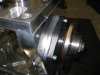
Mark, This looks like what I would want to use for the solid mounts. I'll post it so as to complete the source/idea for later. Thanks.
Cup Rotor, Solid Mount, 12 Bolt & 8 Bolt
Mike, change em, it's not hard and not very expensive.
http://arp-bolts.com/kits/ARPkit-detail.php?RecordID=68
The last thing I am happy about with all this work on the brakes/hubs/wheels is there are NO slots, shims, or wheel spacers at all. It all fits right.
Last edited:
Howard Jones
Supporter
Howard Jones
Supporter
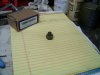
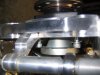
The metric socket head bolts that hold the hub/bearing assembly in the rear upright are difficult to get a wrench onto because of their tight quarters. This little thing drives the socket head and lets me use a big box wrench or a crows foot and a torque wrench (preferred method) to tighten them.
The socket head bolt could be replaced with a normal hex head bolt and achieve the same thing. This is admittedly a small thing but I remember someone asking about how to get clearance on these bolts to remove them and so it follows how to re torque them when they are put back in. This is how I did it and it made it easy.
Cheap simple, and easy! That's how I roll!
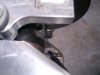
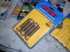
Thanks for the write up on wheel stud upgrade Howard. Your advice worked great on the fronts but it's a no go for the rears. I believe RCR has switched to longer bolts that hold the bearing carriers in place. I was not able to remove those bolts, I thought about buzzing off the excess threads from the other end but the way it is now it has the nice safety benefit that those bolts can never completely back themselves out. I'm going to pull the axle stub.
FYI for anybody else contemplating this method.
FYI for anybody else contemplating this method.
Attachments
Howard Jones
Supporter
How long are the wheel studs you are trying to install? The really long ones that are available were not necessary with the corvette wheels I used. I used the shorter ARP studs in their catalog.
If you push the hub out and away from the upright, can you unthread the three socket head bolts?
My socket head bolts were shorter so maybe that's why I didn't have a clearance issue. They do however complete engage the carrier threads when tightened. Don't go any shorter than that. I have since crossdrilled them all and safety wired them together. I did the caliper mount bolts the same way. Good practice to torque things to known settings and then safety wire them. Especially things that hold the brakes and wheels on.
If you can't get it apart then I would cut them off and replace them with shorter ones before I took the bearing carrier apart. Just too easy to Fup the bearings taking it apart IMHO.
Last edited:
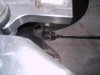
I'm using the same 2.5" ARP studs that are popular with everybody here #100-7708 don't think any shorter would make sense. There is no way to take those bolts out short of cutting them, I spent 30 minutes trying different ways. The extra 1/4" that they stick out is the deal breaker.
I ended up pulling out the stub axles about 1/2" and that gave enough clearance to remove the bolts and proceed with the studs. The stub axle doesn't touch any part of the bearing surfaces so there is no danger in pulling a bearing apart it's just sliding into the hub. It didn't take much effort to move them either probably due to no usage.
I ended up pulling out the stub axles about 1/2" and that gave enough clearance to remove the bolts and proceed with the studs. The stub axle doesn't touch any part of the bearing surfaces so there is no danger in pulling a bearing apart it's just sliding into the hub. It didn't take much effort to move them either probably due to no usage.
Howard Jones
Supporter
Ya, I see your problem with the longer socket head bolts. Whatever you think is easiest for you.
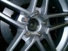
I only needed 1.5 inch ARP wheel studs to work quite well with my Corvette wheels. I have 5/8 inch of stud protruding out of the lug nut with them. Just right.
I only needed 1.5 inch ARP wheel studs to work quite well with my Corvette wheels. I have 5/8 inch of stud protruding out of the lug nut with them. Just right.
Attachments
Howard Jones
Supporter
Howard Jones
Supporter
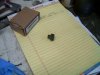
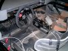
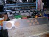
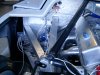
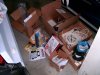
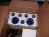
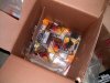
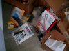
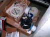
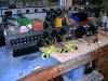
Started wiring the car. So far I have all the sensors located, oil pres, water temp, grbx temp, low oil pres warning, and high water temp warning. I have run wires back to the dash area for the starter solenoid, the sensors signals, alternator output , and battery/starter main power to the master off switch.
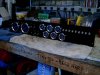
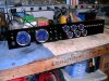
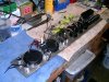
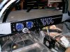
Next was the dash panel. I made it from a piece of alum and cut all the holes with hole saws and a 3/8 drill motor. I have also welded on a couple of plates on the back to make room for the relays and the small power module that runs the lights for the gauges. Kinda tight back there but it will all fit.
No fuses on this car. All circuit breakers. Also all the loads are fed from relays. The small indicator lights on the dash are LEDS
The gauges are from speed hut. I also have a small panel to make that will house a low oil light, high water temp light and the shift light that will be mounted on top of the dash.
Gauges, Custom Gauges, Tachometers, Speedometers, Shift Light, Pod
Here's some pictures.
Attachments
-
 HPIM1956.JPG203.1 KB · Views: 350
 -
 HPIM1958.JPG185.4 KB · Views: 303
 -
 HPIM1955.JPG211.7 KB · Views: 333
 -
 HPIM1954.JPG177.5 KB · Views: 336
 -
 HPIM1960.JPG145.5 KB · Views: 355
 -
 HPIM1961.JPG164.3 KB · Views: 260
 -
 HPIM1962.JPG180.5 KB · Views: 268
 -
 HPIM1963.JPG205.8 KB · Views: 282
 -
 HPIM1964.JPG192.9 KB · Views: 353
 -
 HPIM1965.JPG229.3 KB · Views: 367
 -
 HPIM1966.JPG232.6 KB · Views: 314
 -
 HPIM1967.JPG239.2 KB · Views: 371
Howard Jones
Supporter
Looks great! I assume you already have a plan for labelling the switches and lights. If not, an option is to use cut vinyl. Some Kinkos stores have plotters that take vector image files and cut vinyl rather than print images. They're extremely precise and can produce commercial-quality results. I've used them a lot through the years. I repainted my Harley and created stencils for logos, etc and also made little outlines of the tracks I've driven on to use as stickers for the back glass of my car.
Similar threads
- Replies
- 14
- Views
- 2K
- Replies
- 5
- Views
- 2K