
- Forums
- GT40 Replica Manufacturers' Corner
- RCR Forum - RCR40/SLC/917/Superlite Aero
- The SLC Clubhouse
You are using an out of date browser. It may not display this or other websites correctly.
You should upgrade or use an alternative browser.
You should upgrade or use an alternative browser.
SLC 24 Howard Jones
- Thread starter Howard Jones
- Start date
Howard Jones
Supporter
Well, I agree that would work but I don't have a gopro or a chase car or a place to drive my car other than the track. However, Several drops of light oil on the body where you are interested in airflow are pretty accurate and work better because the data remains on the car until you wipe it off. I have done some of this, and it's pretty clear what is going on. It's pretty much what your mind's eye thinks is going on.
Howard Jones
Supporter
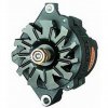
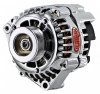
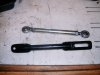
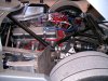
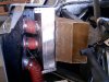
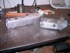
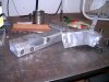
Here is the Alternator tension link that I made to replace the rod end one. I believe that the rod ends allow for just enough lateral movement to flex the alternator housing to the point of fatigue failure. I also replaced the alternator with a newer design that at least looks more robust. The original, that broke, is the first picture and the new one is the second picture.
Attachments
Last edited:
Howard Jones
Supporter
I've had quite a fight with alternators on my track SLC. I have used three different types with the second being the one you have in the picture above. The problem with it was the case broke. See post # 1053. The large 2-inch wide tab with the bolt hole through it completely came off the larger case casting. I believe that the cause was a very rigid lower mount and a double rod end/ tubing adjusting link. The link allowed the main casting fore and aft movement and to flex, ultimately failing.
I am now using a solid 1/4 thick adjusting link with a slot. It is very rigid and I am also using the newest version, the second alternator picture, of the standard gm alternator that looks to have a more robust case.
The first one of the three just shook all the pieces apart internally and burnt up. However, the first one was pretty much the cheapest Chinese piece available. I'm pretty sure it's the curbs at the track that is imparting all the shock loading into the alternators as well as turning them at too high a speed. I have since changed the pullies to achieve a much slower alternator shaft speed as well.
The original alternator pulley was about 2 1/2 inches in diameter with a 6 1/2 inch crank pulley. That was far too small and ran the alternator at near 17000 RPM s with the motor at 6500. I then went to a 3 1/2 inch alt pulley that in theory kept the max speed below the 13000-14000 rpm max but was more than likely far above the designed average duty cycle speed. After all, alternators are really meant to spend nearly all their lives at something near idle and cruising engine speeds. More or less below 3500 engine rpms. This is why they supply 2 1/2 inch pullies with alternators. To keep the alternators turning fast enough to charge the battery with all that modern car electrical load and low engine speed in traffic.
I then called the tech guys at Powermaster Alternators and came to an understanding that about 8 - 10K RPMs max alternator speed would be better so I installed a 5-inch pulley on the alternator and left the 6.5-inch crank pulley in place. This will turn the alternator at about 8500 revs max and about 7500 average per lap.
So maybe that has solved the alternator saga. I now know why you see race cars with driveshaft-driven alternators. It is easy to control alternators revs that way, especially with a very wide rev range and high revving engine.
Last edited:
Howard Jones
Supporter
I have, but there's not a lot of room back there and would require quite a bit of redesign. I hoping to avoid that. I think it will be OK now that I am running it at a far slower speed. This is one of those things that come up when developing a race car. As I have said before I am including all the dirty laundry so that others can see what is involved with running a track car. I like this stuff too!
The thing that I have noticed recently is the last few failure items have been due to fatigue and time on part. Not a failure of my design. At first, I was having things I made break, like brackets. But now it's parts that fail due to fatigue like the older style alternator housing or the MSD distributor rotor. I can see that there is going to be a time-in-use part change-out list.
The thing that I have noticed recently is the last few failure items have been due to fatigue and time on part. Not a failure of my design. At first, I was having things I made break, like brackets. But now it's parts that fail due to fatigue like the older style alternator housing or the MSD distributor rotor. I can see that there is going to be a time-in-use part change-out list.
Last edited:
Howard Jones
Supporter
I went to COTA again on July 16th and ran a 1-day event the started at 3 pm and ended at 11 pm. Five 30 min sessions in total with the first three in full daylight, the 4th as the sun went down, and the last in full darkness with a few lights on the slow corners. This whole thing was pretty stressful as I have never run any kind of race in the dark. I had checked out my headlights and I believed that they would be fine. The thing that worried me was seeing behind me in the dark.
The first three sessions went well with the afternoon air temp in the mid-90s F. I tried to use my phone to get some lap times but it just didn't happen. I'm not a phone guy and I was trying to put in my top t-shirt pocket inside my fire suit. I was having a hard time setting up the track in the app. In any case, when I got home I went on the internet and found a good tutorial on the app. Next time I'll be ready
The app is Track Addict. I think it will work well now that I am more familiar with it. In any case, I am pretty sure I am into the mid 2:30s. One guy with a GT3 Porsche was running 34,35,36s and I was running pretty comfortable with him.
During the fourth session, the shifter began to feel tight. I worked OK and the gearbox shifted normally the shifter just seemed tight. I continued to run the car but it never got better and when I got the car home I found melted shifter cables. More on that later.
Then the darkness came. Oh shit! I couldn't see my brake markers and the corner apexs were gone until you are right on them. OK slow down and work up to it....................right? No fucking way! It was what I was worried about. Seeing behind me. Just a line of headlights on the straights. No way to tell how far back they were and if I waved them thru sometimes nobody would go. Too far back? Then other times the guy was right on me.
I quit after about 4 laps and called it a night. I'm not doing that again.
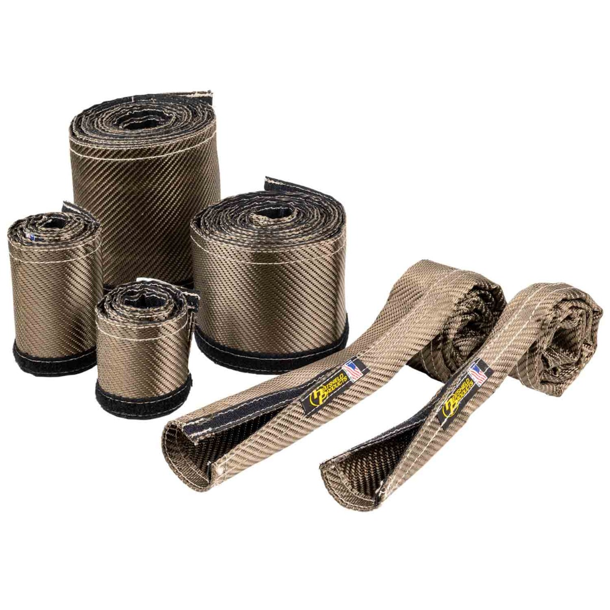
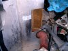
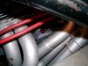
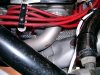
So shifter cables, both are bad. The plastic covering melted even though it was wrapped in heat resistant sheath like this. last pic.
I'm going to use this stuff next time and shield it with a heat barrier. Below.
 www.heatshieldproducts.com
 www.heatshieldproducts.com
The first three sessions went well with the afternoon air temp in the mid-90s F. I tried to use my phone to get some lap times but it just didn't happen. I'm not a phone guy and I was trying to put in my top t-shirt pocket inside my fire suit. I was having a hard time setting up the track in the app. In any case, when I got home I went on the internet and found a good tutorial on the app. Next time I'll be ready
The app is Track Addict. I think it will work well now that I am more familiar with it. In any case, I am pretty sure I am into the mid 2:30s. One guy with a GT3 Porsche was running 34,35,36s and I was running pretty comfortable with him.
During the fourth session, the shifter began to feel tight. I worked OK and the gearbox shifted normally the shifter just seemed tight. I continued to run the car but it never got better and when I got the car home I found melted shifter cables. More on that later.
Then the darkness came. Oh shit! I couldn't see my brake markers and the corner apexs were gone until you are right on them. OK slow down and work up to it....................right? No fucking way! It was what I was worried about. Seeing behind me. Just a line of headlights on the straights. No way to tell how far back they were and if I waved them thru sometimes nobody would go. Too far back? Then other times the guy was right on me.
I quit after about 4 laps and called it a night. I'm not doing that again.
So shifter cables, both are bad. The plastic covering melted even though it was wrapped in heat resistant sheath like this. last pic.
I'm going to use this stuff next time and shield it with a heat barrier. Below.
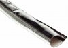
Lava® Tube
Discover the ultimate heat shield tube for optimal protection and performance. Explore our heat-resistant wire sleeve and fuel line heat sleeve solutions.
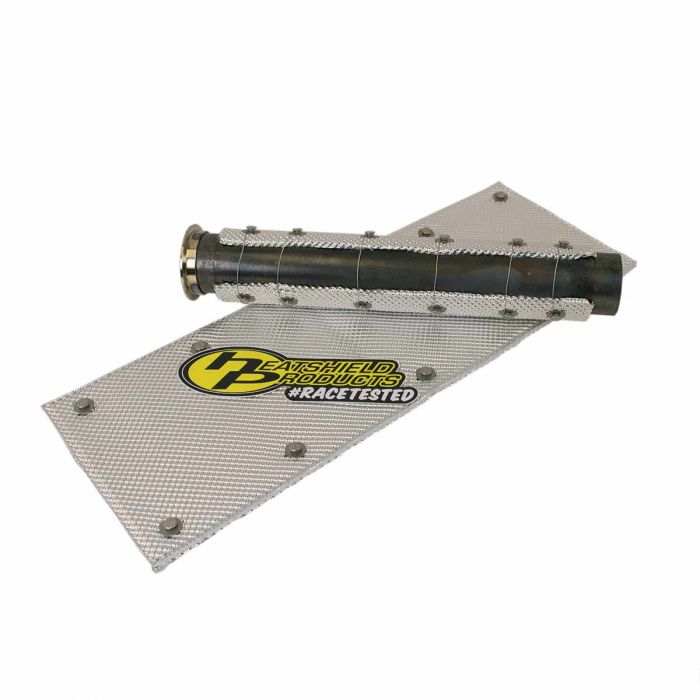
Heatshield Armor® Pipe Kit
Exhaust pipe heat shield reduces radiant heat and protects mufflers, pipes, and nearby components from extreme exhaust temperatures.
Attachments
Howard Jones
Supporter
Dave, No cats. Track only car. This is solvable. It just needs more shielding and I have a plan for that. The cables I melted lasted from the beginning, 5 years and 2000 + track miles.
I think this is a heat-soak problem that is pointing towards the same answer. Venting the rear clam significantly and forgetting about a full covered flat bottom.
If this becomes a chronic problem then a rod shift is in my future. That being quite a project I hope not to have to do it.
I think this is a heat-soak problem that is pointing towards the same answer. Venting the rear clam significantly and forgetting about a full covered flat bottom.
If this becomes a chronic problem then a rod shift is in my future. That being quite a project I hope not to have to do it.
Attachments
The GTM as delivered utilizes a rod shift system designed for the G50. 99% of builders trash it and switch to cable shift. I would try to stick with the cables.If this becomes a chronic problem then a rod shift is in my future.
Howard Jones
Supporter
I believe I can shield the cables from the heat effectively with some development. It's just going to take some thinkin and doin.
Howard Jones
Supporter
yes, I have received a replacement set from Push-Pull Cables in Chico. I think they are of higher quality. What did you guys use on the blue mistress?
Howard Jones
Supporter
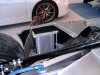
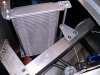
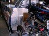
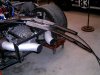
Here are some pictures of the ducting for the oil cooler I came up with. Now that I see what was in my mind's eye I don't like the inlet side so if it's necessary I may just replace all that hose stuff with a fan. For now, however, at least all the oil cooler exhaust air isn't blowing onto the fuel pump assembly, ambient air is somewhat directed and forced to flow through the cooler matrix and the exaust is more or less directed out of the rear of the car.
One of the things I have learned is ducting is complicated to design, fairly inexpensive to make, time-consuming, and absolutely necessary.
Before and after pics.
One of the things I have learned is ducting is complicated to design, fairly inexpensive to make, time-consuming, and absolutely necessary.
Before and after pics.
Attachments
Howard we used a company in Cali that makes a no slack high temp applicable shifter cable. About $100 each cable,
I think it was https://push-pull.com/cablecraft/
Send them an old cable and ask for high temp zero lash.
The grey cables have about 1/4" of play. The high temp cables have zero play..
I think it was https://push-pull.com/cablecraft/
Send them an old cable and ask for high temp zero lash.
The grey cables have about 1/4" of play. The high temp cables have zero play..
Howard Jones
Supporter
Ya that's who have supplied my cables in the past and that's who made the ones I have as replacements now. Interestingly they could make the smaller one with the 3/32 center but not the 1/4 inch larger one in high temp. Could I have used the smaller diameter cable for both? Did you guys use the large cable for the fore/aft movement or use the smaller one for both?
Howard Jones
Supporter
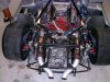
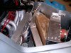
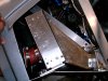
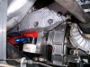
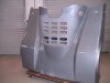
So I spent the last week or so coming up with, building, and installing a heat shield system to protect my shifter cables. As I have said before they run between the engine and driver's side header and there is only about 3 1/2 inches of clearance at the narrowest point. In the past, I tried to just get by with heat sleeving but after some time that failed me. It took quite a while but in the end, sleeving isn't good enough alone. The heat needs to be shielded from the sleeving in some way if the heat is closer than a couple of inches. So here's what I did.
First I made a tray system to run the cables through in the high heat areas. Making the trays fit was a lot of work. Trial cut, tack, fit, repeat over and over. The tray is made of aluminum 2X3 aluminum tubing. Then I shielded the exterior of the tray to cut down the heat transfer. Next, the cables themselves are sleeved with the best sleeving I could find. And finally, I redid the rear engine cover to vent a lot more heat. I am still working on a duct under the car to deliver ambient air to the hot spot. When I finish that I'll post pictures.
For now, here's where I am. Sources/links and pictures are below.
www.heatshieldproducts.com
 www.heatshieldproducts.com

 www.heatshieldproducts.com
First I made a tray system to run the cables through in the high heat areas. Making the trays fit was a lot of work. Trial cut, tack, fit, repeat over and over. The tray is made of aluminum 2X3 aluminum tubing. Then I shielded the exterior of the tray to cut down the heat transfer. Next, the cables themselves are sleeved with the best sleeving I could find. And finally, I redid the rear engine cover to vent a lot more heat. I am still working on a duct under the car to deliver ambient air to the hot spot. When I finish that I'll post pictures.
For now, here's where I am. Sources/links and pictures are below.
Lava® Tube
Discover the ultimate heat shield tube for optimal protection and performance. Explore our heat-resistant wire sleeve and fuel line heat sleeve solutions.
Heatshield Armor®
Heatshield Armor exhaust heat shield blocks radiant exhaust heat to protect wiring, hoses, and under-hood components while improving overall heat control.
Power Anchor™ Kit
HP Power Anchor is a removable exhaust jacket fastener system.
www.heatshieldproducts.com
Attachments

Last edited:
Similar threads
- Replies
- 14
- Views
- 2K
- Replies
- 5
- Views
- 2K