SLC 24 Howard Jones

Howard Jones

Supporter
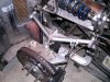
The other thing I had alluded to previously was that the shifter was beginning to feel a bit sloppy. I had also noted just how difficult it is to get the cables out of the car. More on that.

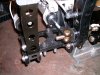
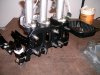
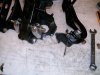
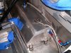
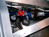
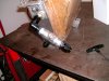
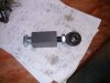
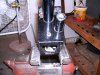
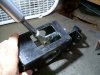
The sloppy feeling was really obvious once I had a look at what was going on. The original design of the shifter box looks to me like the designer stopped working on it before he was done. The main front to rear flat shaft is captured at the front with a bearing and shoulder bolt BUT the rear pivot point is only an 8-32 screw through a hole in the hosing and screwed into the end of the main shaft. Come on, really......... well I fixed that and now with a little cleanup of the other pieces of sharp edges it really works very nicely AND it is now officially battleship built!

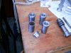
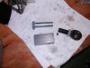
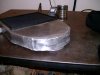
The fix was to install a captured threaded piece of tubing on the end of the center shaft and then screw a 3/8-24 bolt through a 1/2 inch long bearing tube that supports it and into the threaded tubing in the center shaft. It is backed up with a jam nut so it should never loosen. Good to go.

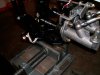
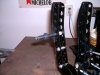
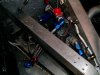
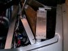
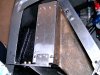
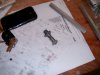
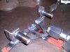
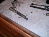
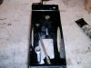
Now the other thing. To remove a cable from the car the entire cable needs to be unscrewed from the shifter box's threaded tube thingie. What a PIA that is. So..................hack them off and locate the cable conventionally with a tab and hole. Now all that is necessary is to undo the rod ends inside the shifter box and loosen and remove the jam nuts on the cable. They then will pull right out of the car now. Easy peasy.

Sometimes I think production engineers should be forced to take things apart once in a while! It's not ALL about ease of manufacturing and per piece cost. Jeese!

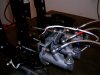
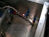
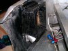
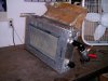
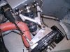
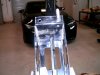
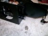
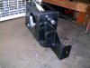
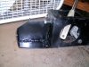
While I was at it I trimmed up a very close-fitting air filter hosing. Plenty of clearance to the bodywork now.
 

Attachments

  • HPIM2540.JPG
    HPIM2540.JPG
    787.9 KB · Views: 354
  • HPIM2541.JPG
    HPIM2541.JPG
    830.3 KB · Views: 346
  • HPIM2542.JPG
    HPIM2542.JPG
    969.1 KB · Views: 306
  • HPIM2545.JPG
    HPIM2545.JPG
    761.7 KB · Views: 278
  • HPIM2546.JPG
    HPIM2546.JPG
    689.9 KB · Views: 286
  • HPIM2547.JPG
    HPIM2547.JPG
    939.4 KB · Views: 280
  • HPIM2548.JPG
    HPIM2548.JPG
    908.8 KB · Views: 272
  • HPIM2549.JPG
    HPIM2549.JPG
    848.1 KB · Views: 277
  • HPIM2550.JPG
    HPIM2550.JPG
    799.5 KB · Views: 313
Last edited:

Howard Jones

Supporter
Since the end of last season, I have been working through a few punch list items.

I have gotten to the point that I believe that the brakes are working pretty well generally. But I had two 5/8 diameter master cylinders in the car and that small of an MC causes a bit more travel than I like. Not soft but longer travel. The only way to correct that would be to increase the size of the master cylinders but I originally had 3/4 MC in the car. Well, .7 inch masters are available so I changed them both to .7 diameter.

When I took the peddle box out of the car I found a crack in the main casing in the area of the throttle arm. Shit! I welled it up and it came out pretty good but I couldn't sleep well with a welded-up peddle casting, especially since it's a heat-treated aluminum alloy so I sprung for a new Tilton peddle box. Guess what? yea they are not exactly the same. It took several minor modifications to get it to work with the current throttle cable arrangement as well as a few other little things.

I don't know about you all but working down in the footwell really sucks......a lot. So I made the new mounts for the peddle box so that all the bolts are captured in a way that they do not need to be held inside the car and the nuts tightened from the bottom, I did this by welding a link between the bolt heads so that now the entire peddle box can be dropped into place and the nuts on the bottom of the car can be tightened without any help from above, A lot of work but from now on removing the peddle box is an easy one-man job.

Elsewhere I had to address the tow loop mount. The tow truck safety crews tend to work very fast and tow points get huge loads when the tow truck hauls ass off the track and back to the paddock. The original tow loop is made of steel and bolted through the top of the foot box. The aluminum foot box had flexed and deformed quite a bit. It is just not strong enough to feed this amount of load into without any additional support. So I had a long think on the problem and came up with what I believe is a good fix. Below the foot box roof, inside the car's footwell, above the peddles is the roll cage cross brace up in the top front of the foot box. So I made an additional attachment support that not only bolts the tow loop to the top outside of the foot box but also continues through it downward and attaches to the roll cage. This entire assembly is very stiff now.

Then onto the main event for the winter. I have made a few changes to both the front and rear bodywork over the last few years. There was the shunt repair to the front, some fiberglass work to the radiator inlet area, and some damage caused by track debris. On the rear of the car I have come to the concussion that the rear cover over the engine needed a lot more ventilation. So I filled in the original holes that were in place for the scoops and then added several vents to the cover itself. While I was t it I again changed the shape of the airfilter housing where it was slightly rubing on the body work.

I looked around and found a painter that would do a repaint of only the front and rear body pieces. I took all the hardware off of these and hauled them over to them in my enclosed trailer. That made it really easy. I used MACCO auto painting. They worked with me to keep the cost inline with my track car quality needs. I used a paint code that is standard for a Mazda something or other. The choice was to try and match what was on the car or pick a production color and when we talked about it we both came to the conclusion that a production color that was as close as possible would be much easier to use again next year when I repaint the center of the car. It came out pretty good for now and they took the time to apply a skim coat of filler where it was needed to fix chips as well and a full sanding of the body parts as well as apply a full undercoat so that he would be able to warranty the paintjob. Pretty good for $689.00 all in.

First the peddle box then the bodywork pictures.
 

Attachments

  • HPIM2551.JPG
    HPIM2551.JPG
    949.7 KB · Views: 254
  • HPIM2552.JPG
    HPIM2552.JPG
    775.3 KB · Views: 237
  • HPIM2553.JPG
    HPIM2553.JPG
    688.4 KB · Views: 231
  • HPIM2554.JPG
    HPIM2554.JPG
    799 KB · Views: 235
  • HPIM2555.JPG
    HPIM2555.JPG
    861.2 KB · Views: 231
  • HPIM2556.JPG
    HPIM2556.JPG
    767.1 KB · Views: 258
  • HPIM2557.JPG
    HPIM2557.JPG
    794 KB · Views: 270
  • HPIM2558.JPG
    HPIM2558.JPG
    746.7 KB · Views: 261
  • HPIM2559.JPG
    HPIM2559.JPG
    837.9 KB · Views: 250
Last edited:

Howard Jones

Supporter
I went to the track on Sunday the 30th. It was a pretty cool day with air temps in the 60s and low 70 mostly. I had a really hard time getting the tires to heat up. In the two morning sessions, it was particularly difficult with very cold track temps and a dirty track. We were the first cars on track at COTA this year and there was no rubber laid down except the Saturday sessions.

I have also started to try and get some track lap times using my phone and an apt called trackaddict. I am an old guy and NOT a phone guy but I did get it to work for me. My best lap before lunch was a 2:41 which I consider rather slow for me and what I know the car is capable of. The last session of the day was 4 Pm -5 Pm and warmed up the track surface. As the track came in a bit and I had worked out the revised brake bias since I changed the master sizes and generally messed with the peddle box/bias bar I did get down to a 2:36. There is quite a bit still in the car but for now, that is my best recorded time at COTA.

I like the larger masters. There is quite a bit less travel but still not too firm of a peddle that required a gorilla leg to stop the car. I am pretty sure I am done with the brakes.

I have come to the conclusion that the car needs another 100 horsepower. I can run down some pretty fast cars in the eses, in the corners, and under braking but they just run away from me on the long straights. When I started to build this car you couldn't buy a 600-700 hp streetcar. Now a Camaro as well as others are just rockets in a straight line. At about 450Hp I just can't stay with them and will be passed only to be back on their bumper and waved by in the twisties elsewhere on the track. This gets frustrating because it will tend to slow us both up over the lap.

Looking at a 400CI 550-600hp motor build to replace the 355ci /450hp in the car now. More on that as the idea begins to become hard parts. I am sure I want to run on pump gas and use a Hyd roller cam and stay with the SBC template so that the rest of the car will not require a redesign. I talked to California Motorsports and Rodger said my gearbox would be Ok at 600Hp. We'll see where this goes but I am thinking a DART block with a 4.125 bore might be a good basis for a 400/ 11 to 1 motor with more cam. The question is will I be able to reuse my heads. I am going to talk to the engine guy up the road this coming week and see what we can do without spending 20 grand on a motor. He does TRANSAM engines and would love to sell me a $40K engine but I just can't justify that kind of scratch for what is essentially a toy.

We'll see.
 
Last edited:
I did get down to a 2:36

Without video proof, it didn't happen. :p

150hp increase? - you should notice that.
Are you still accelerating at the end of the straight? If yes, then a reduction in weight would be helpful as it will get you to speed sooner.
Shorter gears will get you there faster, might take some load off the gears as well (?)
 
Cylinder heads are the #1 denominator for useful power. Its all about air flow. Both of which I think you already know. I really enjoy and have learned so much from watching Engine Masters on Motor Trend Network. If you are looking to configure an engine around a certain set of heads you may be able to cherry pick episodes based on what you have to optimize the choices you have to make to reach your goals.
P.S. What heads are you currently using?
 

Mark B.

Supporter
+1 to Rich on heads being the #1 factor (along with cam selection of course). I ran a 370 SBC in my Corvette. Factory 4-bolt 350 bored 30 over with a 3.625" crank. AFR 210 heads and a moderate hydraulic roller cam which made 550HP/ 486TQ on the engine dyno. You could keep your block, get a 3.75 crank to make it a 383 and spend the money on heads instead of a new block.
 

Howard Jones

Supporter
The heads on the car now are IK200 Brodrix Aluminum heads. 2.02/1.60 int/ex. The heads or lightly ported and have a very well-done 5 angle valve job. CR is 10.68 to 1 and the cam is a comp hyd roller cam 294 dur @ 550ish lift on intakes and 300 dur/550ish lift of ext. This motor makes 1.25 or so hp per inch (438 hp- 448hp) on 93 octane pump gas and is limited to 6200 RPMs.

This is really a pretty good motor but I think trying to get to 1.6 Hp per inch or more on pump gas with 350 ci is not going to fly and remain reliable. The rotating assembly is a forged scat one and it is one of the good ones so I hate to take it out only to save the chevy block that in reality isn't worth much.

I am thinking that I might be able to reuse my heads with a few hours of port work as well as my valve train on an 11 to 1 400-inch motor. If it still makes 1.25 hp per inch then I would be right at 500Hp but I want to talk to the engine guy about this again about how much he thinks I need as far as port flow to get to 550Hp. That would be +100 hp from where I am now more or less. I am thinking that 11 to 1 CR and the port work ought to be worth something and that just might put me at or near my target of 550HP maybe a bit more. I think it would take more cam to get much more than that.

The other way to go would be to use new heads and valve train and go all-in with a complete engine, then sell my old one. Either way is pretty close to the same amount of money assuming I can get a fair price for my existing engine.

I should say that I am firm on retaining a hyd roller cam and running it on pump gas.
 

Mark B.

Supporter
Yea those are good heads -- no need to change them. Invest in some good porting, increase your stroke to 3.75. Cam selection will be key, but no reason you can't do 550+ on pump gas with 11:1.
 

Howard Jones

Supporter
Did COTA again on the 16th. Very nice day was warm with low 80s in the afternoon. As I have been going a bit quicker and trying to really use the brakes I have noticed that the harder I push the pace, the more balance bar adjustment is required. I believe that when running in the low 1:40s I'm not working the brakes hard enough to equally heat up the pads at the same rate front to back. Interesting the rear seems to have come up first but before the rear tires did. That's what that first snap oversteer was I believe. I adjusted the balance bar a few times after that to add more front and it seemed to have a better balance F to R.

There's a lot to learn with this build you own race car hobby. A LOT more than just picking cool parts and putting it together. Later in the video, this is session #4, I was chasing a Mazda Miata with a rotary in it and did a couple of 37.1s. Then I started getting a fuel starvation thing happening and I almost thought it was running out of fuel but the gauge looked like there was plenty so I keep going. Those two 37.1s were the best of the day as it looks like the fuel pump is dying or maybe the pressure regulator is f'ed up.

It started to get worse in the last session so I wasn't able to improve on my times for the day but I am more confident than ever I can get down under 2:35. New tires and more power .....................20s .....................well we'll see.

Oh and a bit of a surprise on the last lap.

 
Last edited:
Now thats a great complement to your morning hot chocolate! Iyyeeee like it.
Easy to tell the confidence is "strong-like-bull" compared to earlier vids, way to spank those Mazdas you show'd 'em good. The hot looking McLaren M8 was a nice surprise, shame it wasn't up to speed.

Nice driving and shifting.
Awe man, can't wait to get out there with you.

Thanks for the vid, made my morning!
 

Howard Jones

Supporter
Figured out the fuel feed problem. The pump is a dc armature and bush design, not a brushless, One of the two brushes cracked in two and was causing the pump to lose torque intermittently. It hurt the commutator a little but with a couple of hours of careful clean up I got it to dia indicate nearly perfect. The pump is a Mallory 140 and the new cost is about $400 so it was worth it to fix it.

An interesting side note. I bought a Holley black pump as it has the same flow rating of 140 GPH thinking I could simply mount it in the same location and get on with it. No joy. The Holley would not draw fuel up and out of the fuel tank like my Mallory did. In my car, the fuel pump inlet is about even with the empty fuel level in the tank but the route is straight up to the top of the tank, about 12 inches vertically, from the bottom of the small sump I added in the fuel tank, across the fuel tank compartment, through the bulkhead and then down to the pump inlet after being plumbed thought the fuel filter. Maybe 4-5 feet in length altogether.

So I had to fix my original pump. Lesson learned. All of the rotary vane-style pumps like the Holley and most others must be located below the fuel level in the tank with a downhill route to the pump inlet. The Mallory is a different design called gerotor type. Here's two videos of each type:


At the same time, I decided to change the fuel system to a return type so I bought a return type regulator and plumbed it into the system. The bottom line is the dead head system style is simpler but I believe the return type has some advantages such as circulating the fuel out of the engine room and back to the tank to help with vaporization in the fuel lines and the fuel system. These cars really run hot in the engine room and every little bit helps.

I will add some pictures later when I get back out in the garage this afternoon. I also finished the oil cooler inlet ducting so more pictures of that too.
 
Last edited:

Neil

Supporter
Howard, most vane pumps sling their vanes out by centrifugal force so if they get gummed up, the vanes stick and can't create a vacuum to lift fuel to its inlet. Try disassembling the Holley pump end and clean the vanes & slots. The Mallory is a better pump, though.
 

Howard Jones

Supporter
The Holley pump is brand new from Summit, already sent it back. I think you are right, the Mallory is a better pump. But it is louder and costs twice as much. I kind of like that I can hear it running from the driver's seat when I turn it on.

Here are the pics. First is the revised pressure regulator and its plumbing. The third shows where I pick up the fuel from the top of the tank and the other hose is the return from the pressure regulator. Then the new ductwork, and finally a little thing I made to house the oil temp sensor. Now I will be able to see the actual oil temp being returned to the motor after the cooler. Before it was in the oil pan and it read the oil temp of the pan volume. I think it is more important to know what temp the oil is being delivered to the main bearings and the rest of the motor. I choose the oil cooler outlet fitting for the sensor housing location. From there it goes right back into the motor main oil galley after being pumped from the pan, through the filter, and then to the oil cooler.
 

Attachments

  • HPIM2561.JPG
    HPIM2561.JPG
    848.5 KB · Views: 159
  • HPIM2564.JPG
    HPIM2564.JPG
    812.7 KB · Views: 147
  • HPIM2565.JPG
    HPIM2565.JPG
    927.7 KB · Views: 139
  • HPIM2566.JPG
    HPIM2566.JPG
    879.4 KB · Views: 134
  • HPIM2562.JPG
    HPIM2562.JPG
    1.1 MB · Views: 140
  • HPIM2563.JPG
    HPIM2563.JPG
    862 KB · Views: 132
  • HPIM2567.JPG
    HPIM2567.JPG
    921.5 KB · Views: 131
  • HPIM2568.JPG
    HPIM2568.JPG
    860.5 KB · Views: 153
Last edited:

Howard Jones

Supporter
I never posted pictures of the completed oil cooler ducting fully installed on the car. So here they are. As you can see earlier in the thread I had originally not had any oil cooler ducting. Then an unusual setup using two pieces of brake cooling hose for the inlet side that really worked better in my mind's eye than in reality. What is now on the car is much more traditional and I am sure will work much better.
 

Attachments

  • HPIM2569.JPG
    HPIM2569.JPG
    813.5 KB · Views: 141
  • HPIM2570.JPG
    HPIM2570.JPG
    982.1 KB · Views: 165

Howard Jones

Supporter
Don, I did look at that one! I called Summit and the tech guy wasn't sure if they will/would pump uphill. I didn't do much more research after that because I needed it to self-prime and lift 18-24 inches and I knew the Mallory types would. I did buy another Mallory pump and will keep the original one as a spare in the trailer. So I will never need another one per Murphy's rules........I did find out that most electric fuel pumps will not "lift fuel".

Oh.......................... from the Carter website "

ROTARY VANE
Originally created for military use, this configuration has been in production longer than any other Carter model. Rotating vanes driven by a heavy-duty wet motor deliver pressure from 4 to 18 psi at a flow rate of up to 100 gallons per hour. This provides excellent lift and prime capability. The pump is available in 6-, 12- and 24-volt versions. It is appropriate for RV, marine, agricultural, industrial and performance applications.

So I guess they will. The black version is a rotary vane type. Thanks for the heads up,
 
Last edited:
1654704578495.png
i have been running a pair of cheap walbro fuel pumps in my Ultra 4 rock racer for 8 plus years. the2nd pump is there as a spare. but in 8 years the original has not failed. these pumps have a check valve but they start dry every time the car has been sitting for more than a day. I hear the pump sucking dry for about 10 seconds before it is able to pressurize the fuel system. the pump sucks fuel from 2 feet below the pump. there is no separate swirl tank in the system and the pump is ran in a constant fuel loop. (not using a corvette LS style pressure regulator) Submerged sump pumps are ideal but a dry pump pulling uphill can still work. And having the fuel pumps out of the tank makes service much easier especially in a race car
 

Howard Jones

Supporter
I may have alluded to a handling characteristic for which I was having difficulty understanding and finding a solution. What is going on is, under hard braking, at high speed, the car seems to go to a loose condition as the rear of the car pitches upward. It just seems to be rear steering but in an unpredictable way. I say rear steering because I can't think of another way to describe it. This condition isn't present braking hard under 100 MPH. Just at top speed as soon as the brakes are applied hard. Then it goes away as the car settles on the suspension. It seems to me that the aero download is depressing the rear of the car and as the brakes come on, the nose goes down, the rear aero starts to go away and the rear comes up. Then the rear tires/grip seems to "hunt" for a direction it wants to go, but just for a moment,

So I convinced myself that it was related to toe change as the rear goes full droop. I tried to measure this statically in the shop and did see some toe change from the target setting of 1/16" in, to a little above zero or even just a hair positive at full droop. The other way, full compression stays pretty good and remains at zero or just a bit negative. I could set to 1/8" in both sides to eliminate this but 1/8" in on the rears seems a little excessive to me,

So I decided to move the toe adjustment to inline with the upper A-arm plane. Now the toe setting MUST remain as set as the upper A-arms moves up and down with suspension movement because the toe link and the upper suspension remain in the same plane. All the real racecars, including the RCR SLC national champ car, do it this way and in fact, the optional race suspension is where I got my inspiration as well as some advice from a friend.

So while I was at it I have been wanting to incorporate a camber adjustment in the upper A-arms for quite a while So I did that also at both the front and rear. No more taking the suspension apart to change the camber, Just loosen the jam nut and turn the big collar. Check camber, reset toe, and done.

Everything is 4140 steel, cold rolled steel, or made from a grade 8 bolt. The collars are big grade 8 bolts turned and center drilled then threaded. The one thing that was difficult to work around and keep all the upright parts unmolested was the attachment hole for the inboard toe link at the rear. In the end there's really very little space to work with and so I made a two part collar to fit in the top plate of the upright and then threaded the bottom half to allow for clamping like the original bolt and nut did. This forced me to use 3/8 rod ends and hardware but when I see Indy cars using 3/8 sized rod ends throughout the suspension links on their cars I think I will be fine. I did buy chrome molly high strength, high misalinement rodends and I used grade 8 hardware. The link adjuster is going to get replaced with a much larger od piece of material when I get to it. I needed to make something to finalise dimensions so I used a at-hand piece of tubing and threaded it LH/RH.

Heres some pictures: The first one is all the bungs in the inboard ends of the A-arms, then the center bosses front the front and rear before they got turned down to their final profiles, the front A-arm in situ, the little two piece collar for the rear toe link outboard attachment point and finally the rear in situ. Lastly, is the jig I made to align everything while I welded them so that I could duplicate the original aluminum A-arms dimensionally.
 

Attachments

  • HPIM2580.JPG
    HPIM2580.JPG
    849.4 KB · Views: 100
  • HPIM2581.JPG
    HPIM2581.JPG
    736.3 KB · Views: 99
  • HPIM2582.JPG
    HPIM2582.JPG
    746.3 KB · Views: 99
  • HPIM2588.JPG
    HPIM2588.JPG
    973.3 KB · Views: 98
  • HPIM2585.JPG
    HPIM2585.JPG
    679.9 KB · Views: 99
  • HPIM2590.JPG
    HPIM2590.JPG
    998.3 KB · Views: 102
  • HPIM2584.JPG
    HPIM2584.JPG
    919.4 KB · Views: 101
Last edited:
Back
Top