The Regeneration of a Once Loved and Unique GT40

I've lowered the chassis at the front, shortened the back and measured things up so that I know roughly the body is going to fit. The only issue I have is that the engine is sitting 40mm too high, making it all difficult with the rear window of the rear body section. If I can get the engine and body relationship to be as the Tornado car then I can use their exhausts too.

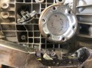
I check with Andy Sheldon at Tornado and he gives me some critical dimensions. It definitely needs to go down 40mm. Obviously the lower the engine goes the better anyway. I had previously got it as low as I could given the restraints of the output shafts and the chassis rails. Here is my problem, the only way to get it lower is to cut out the chassis to allow the output shafts to go lower but it is all right where the lower wishbone mounts are. It's going to require cutting and strengthening in a different way. Not only that, I need to do the same with the cross member to allow the transaxle to drop by 40mm.

IMG_1868.jpg

I've got to go down 40mm and maintain the integrity of the chassis

IMG_1869.jpg


IMG_1870.jpg


IMG_1879.jpg

Out with the grinder

IMG_1882.jpg

I plasma cut out enough material to allow me to drop the 40mm

IMG_1884.jpg


IMG_1885.jpg


IMG_1886.jpg

Looks better now!

IMG_1887.jpg

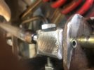
I weld in new rails behind and create room for the bell housing to drop down by sculpting the new chassis rails

Having created the space I then turn to the actual engine mounting rail. That's in the next post as I have reached my picture limit!
 

Attachments

  • IMG_1883.jpg
    IMG_1883.jpg
    105.8 KB · Views: 37
I decide to cut and drop the rail I had previously added for the engine mounts. It is in addition to the previous chassis and purely carrying the motor and cutting and dropping minimises rework. None of it will be seen, just needs to be tidy and do what it needs to do

IMG_1905.jpg


IMG_1904.jpg


That's it, all done and now I can drop the engine. I just need to reconfigure the gearbox mounts but that is pretty straightforward. Now it's in as low as it can go and everything is welded up and tidied. I had a problem with my welder which was a pain but got there in the end after purchasing a new spool gun.
 
The engine is in, I know the body can be made to fit, time to look at some of the other aspects. I borrow a set of exhausts and have a trial fit. It's all very tight around the slave cylinder area. I wish now I had bought one of Tornado's purpose made bellhousings as that moves the slave underneath the exhausts. However, I am now committed to the adaptor plate and UN1, especially as I have had all the rotating assembly balanced including the small flywheel.
I will adapt the pipes a bit and use some top quality insulating material between the slave and the exhausts.

IMG_2578.jpg


IMG_1911.jpg

I now know it will all fit and I order a set of exhausts from Tornado, ceramic coated in gold. Gold because at this point I have decided on a black and gold livery.

I also look at the front end and sort out the steering. I decide to ditch the power BMW rack and go with a Ford one, mounting the rack at a height which according to my race car suspension expert buddy will be neutral on bump steer! To be sure, I build in adjustability. This will allow fine tuning if needed.

IMG_2684.jpg


I make sure the steering is in the right place for me inside the car and mount it on a new bearing. Again, I make the mounts all adjustable so that the steering wheel can be moved up, down and both right and left. I set it for now, where I think would suit me.

I also make the steering wheel removeable using a Lifeline boss

IMG_2739.jpg


IMG_2740.jpg


IMG_2742.jpg
 

Randy V

Moderator-Admin
Staff member
Admin
Lifetime Supporter
Great progress Chris! Be careful with exhaust systems as we've found there is no standard routing or clearances between builders. I would hold off on having the exhaust coated until after you've made sure the pipes fit to your satisfaction..
 
I now start altering the rear suspension in line my friends calculations (mentioned earlier). I need to drop the top link 40mm to get optimum performance which means cutting and welding the upright and the chassis mounts. Later I decide to remake all the wishbones and tie rods on the rear too.
I mark up roughly where we need to be and get that grinder out again!

IMG_2771.jpg


IMG_2781.jpg


IMG_2782.jpg


IMG_2783.jpg


IMG_2784.jpg


IMG_2785.jpg


At some point I take the uprights off and drill out as much of that thick metal as I can to reduce weight and make them look more like a GT and less like a tractor but I seem to be missing any photographs of that. I will post a set at the end of the finished car.
With help from my friend, we re-make all the arms too

IMG_2858.jpg


IMG_2859.jpg


IMG_2861.jpg

A little grub screw holds the mount vertical and stops any twisting
 

Attachments

  • IMG_2861.jpg
    IMG_2861.jpg
    61.7 KB · Views: 35
At this point in my build I decide (on a whim) to buy a Powder Coating gun and an old Lab Oven from EBay. My fabrications are transformed and it proves to be the best tool I have ever purchased. My first powder coating is the new rear wishbones

IMG_3332.jpg


IMG_3333.jpg


IMG_3334.jpg


At the same time I make up front and rear anti sway bars. The rear one is from a Westfield (Lotus 7) and I cut it and extend it to fit. The front I fabricate out of the spare tube bought for the wishbones. These are too long for my oven so spray paint will have to do but at least I can get the drop links powder coated and baked!

IMG_2817.jpg


Cut and extend the rear sway bar using seamless tubing sized to match

IMG_2819.jpg


IMG_2820.jpg

I weld the bush fixing plates to the chassis rail

IMG_2821.jpg

On it goes (will cover the exhausts in a later post)

IMG_2803.jpg

Make up some drop links for the rear (new wishbones not fitted yet but they are made with the same mounts)

IMG_2813 (1).jpg

Ignore the top link in the background - it's temporary!!

IMG_2736.jpg

I insert a new cross member in the front to support the front sway bar which is connected by arms to the rockers of the front suspension. Obviously this is different to most (all??) GT40's but I think it will work OK. Everything is fabricated to suit this car. The bar is 1 inch tube, seamless. The arms are just cut from 5mm stock. The shocks will be later replaced with new purpose made ones.
 

Andrew

Supporter
Great progress! I've been an avid reader since you started this thread.

What powder coating gun did you go for out of interest? Also what oven did you find?... wishbones are pretty sizeable!
 
Great progress! I've been an avid reader since you started this thread.

What powder coating gun did you go for out of interest? Also what oven did you find?... wishbones are pretty sizeable!
I bought an ElectrostaticMagic gun at a show. https://www.electrostaticmagic.co.uk. I was standing looking at them when a guy came up and said 'if you are thinking of buying one just do it, I've had one for years and it's the best thing I ever bought'! So I did, and I have to say, so far, I agree with him. I started out using the wife's oven but quickly switched to a lab oven I found on EBay, not because the wife was moaning, but because it was a lot bigger. Total investment for gun and oven was around £250. Believe me, they are absolutely brilliant and you will see what I have done later on as my posts show overall progress.

IMG_3357.jpg
 
How do you cut and rewelded a sway bar and not ruin the temper of the spring steel?
I think you know the answer to that one! You can't, at least I don't know how you could. But, I have done it previously and not found it to be a problem. My buddy, who has built many a race car, told me he has done it many times too! I'm sure the heat effects it but not too detrimentally. If they crack, I'll post it on here and will then have to have a re-think!! (my cobra has had a welded one on it for 40 years btw and that has been driven very hard indeed)
It would be interesting to hear if others have done it too and whether it worked for them or not.
 
I crack on with the panelling using 2mm aluminium, fabricating and welding up panels as required. I am using fireproof insulation in all the cavities in an attempt to minimise noise and heat transmission, putting it everywhere around the cockpit area. I decided to run the water pipes down the LH rocker and insulated them well too thinking this might help keep things a bit cooler in the cockpit. I have to sculpt out the panelling around the distributor area to give enough clearance (already mentioned earlier during engine install post). I also make panels to cover the tank sender and the battery. Things progress!
Observant people will notice that there is no rear window in the bulkhead. I decided to omit that too in the interest of keeping noise and heat out. Later I will show you my solution for rear view.

IMG_2874.jpg


IMG_2875.jpg


IMG_2945.jpg

The fuel tank sender is under here. It was a BMW unit (which I later change) and part of the high pressure system required for the injection engine that was in the car previously. I pondered cutting out the boss and rewelding lower in the tank (which is in stainless steel) but decided against it partly for safety reasons partly because the tanks are good and I just didn't want to risk a leak. I have welded used tanks before but a friend once lost an eye when he got it wrong and ever since that, I tend to avoid it if possible! These things play on your mind!! He was actually lucky, damaging his skull too. It could have been worse.

IMG_2966.jpg

Battery box and isolator switch. Rear panels around wheel arch are done here too. I later discover that I can turn that isolator on and off by putting my arm through the air vent. It wasn't planned but it's useful!

I make up a little header tank in aluminium, or more accurately, I weld a different mounting system to a little tank from a cobra and shape it as I want it! You might be noticing I have a passion for re-purposing things. Sometimes it works out and sometimes it doesn't!

IMG_2973.jpg


IMG_2974.jpg

I look at the front in the next post (the spider isn't fixed btw, hence the gap!)
 
On to the front end. Radiator in. It's the one that was in the car when I bought it. It's old but decent and usable, I can upgrade to an aluminium one when I need to. I start getting the panelling on and fit the Davies Craig water pump. I need to make up bracketry to keep everything supported but the routes all work. As you can see, I'm running the water pipes down the side pod.

IMG_3019.jpg


IMG_3017.jpg


IMG_3031.jpg

Under the stepped panel is a little cubby hole! Unfortunately not big enough for my T-Tops but I might get some underwear, a toothbrush and a sandwich in there! Or some spanners. Anyway, a bit of space for something.

IMG_3169.jpg

I welded up the main panel in to one large piece. It was a bit tricky as there were lots of shapes and corners but got there in the end. I start looking at the interfaces with the body. With some fettling I am confident I can get it pretty decent.

IMG_3170.jpg

Pipework brackets fabricated and fixed. Latches put on the cubby hole lid. Later I line the storage box with insulating material too.

IMG_3572.jpg

Then of course, having made everything, you have to take it all to bits and get some primer on it!

IMG_3627.jpg

And eventually, after lots of work, it starts to look better. I added the adjusters to the top wishbone so I can adjust the suspension without taking the rod ends out. I drilled out the wishbones to put the adjusters right through. Fortunately there was plenty of meat there. What I don't know at this point is that I will also need to do some work on the bottom wishbone. Should have twigged it really but sometimes the easy option (doing nothing!) is too tempting! I'll share what happens in a later post.
Nothing is spaced yet, I will do that when the body is fitted but there is plenty of scope in the bracketry to give me some flexibility with alignment.
The wishbones are powder coated with my new gun! As are the radiator pipework brackets you can just see in the front. The rest is painted with bed liner.

IMG_4001 (1).jpg

I'm now really getting in to the powder coating. I take the fillers apart and coat them up in my black and gold colour scheme. The quality and potential of the powder coater starts to dawn on me. It is so much easier than painting. I can make a bracket, coat it and within 10 minutes have it on the car. Not only that it looks better and is harder wearing. It's going to make quite a difference to my build.
 
I now have a go at powder coating other things and the work I have done but not put paint on. I start with the steering wheel.

IMG_3387.jpg


Then I have a go at the brake calipers, refurbishing the BMW ones that were on the car. I blast them, clean them up and add new seals after coating

IMG_3408.jpg


IMG_3409.jpg


I also have a go at the backplates and hubs, cleaning everything up first. The BMW rears are really good as they have an effective handbrake inside the disc

IMG_3520.jpg


Then I remove all the panels from the rear of the car and powder coat them. I can just get most of them in the oven although it's a bit of a squeeze and challenging not to mark them getting them in, but with perseverance, I get there! I also coat the hub carriers and the drop links and my little header tank. By this time I have drilled out the hub carriers to make them lighter but really for aesthetics - they just look better now I think!
I get my new wishbones and tie rods fitted. Again all powder coated. Getting the tie rods in the oven was really tight and required me removing the back panel of the oven to get the last few mm in there!
I started out using heat resistant masking tape but later discovered that ordinary masking tape works just as well, is easier to put on and a lot cheaper. You do need to keep the powder out of the threads or clean them with a die afterwards (the former is better). With practice I get better and more confident. I replace all the rod ends with new ones form McGill Motorsport (a really good UK suppler where I buy a lot of stuff)

IMG_3527 (1).jpg


IMG_3529.jpg


IMG_3570.jpg


The exhausts are ceramic coated (not by me!). I do actually later have a problem with the finish. I like it but unfortunately it loses adherence on a couple of pipes later when I do the cam break in and I have to send them back. When they return they are in a matt finish which is a shame but the shiny one just didn't seem to work for some reason. You will see the matt ones in later posts. I also remove the inlet manifold later and coat that gold too. Then I also fit a black carburettor to keep with the colour scheme. But that's for later.............
 
I think I mentioned previously, some of the welding on this car was really good, but some was truly awful. Here is a picture of what was going on under the old dashboard. There is no doubt it needs tidying up!

IMG_2762.jpg


I cut out the rubbish and add some new stainless members in and start tidying up the mess in order to get a suitable mounting for the new dashboard and to properly support the upper bearing for the steering

IMG_2764.jpg


IMG_2766.jpg

Part complete. I sort out the steering mount but don't seem to have a picture of that

Dashboard in for a trial fit. I have to remove the plywood stiffeners bonded in to the Tornado dashboard at the mounting points as these are too thick for my car. Instead, use some aluminium sheet bonded in. This gives me just enough movement to get the dashboard forward enough without altering the existing bracketry.

IMG_2767.jpg


Eventually, I can get the instruments and switches in having made up some aluminium panels that I will powder coat gold later. The dash is supported by a jar of my honey!!! Another hobby!!

IMG_4356.jpg
 
On to body fit. Oh my, the hours and the fiddling! My challenge is two fold, 1. I have never built a GT40 before and 2. This is a one off chassis and the body is not made to fit it! The former, MK3 body, was very different. I have no useable mounting points left on the chassis, the rear ones having gone when I shortened it and the fronts were useless.
The spider position is pretty well defined by the bulkhead and wiper motor/windscreen position. Of course, I can move the wiper motor position if I need to but take the line that it worked on the previous body so should (!) work with this one, at least in relation to the spider sitting in the right place.
I drill the wiper motor hole and drop the spider on, using the wiper motor as a location point.
I've got a few dimensions from various sources including this forum to help me get things in roughly the right place and I check back to the rear of the rockers, the width and height from the chassis to spider at door hinge area. I will worry about door hinges when I get the rest fitted. The existing hinges are just rubbish and the Tornado doors are a different design anyway. The rod that drops down through the door is smaller than the one on the existing car so the holes are all too big anyway, even if they are in the right positions which is unlikely as the doors were previously a different design.
I'm a little concerned that if I positively fix everything that I will end up doing re-work, so I try to make everything adjustable to allow for fine adjustments later. This proved to be really valuable.

I start by making up some reinforcing plates in stainless to stiffen the body where the mounts will go and then some hinge points that attach to the chassis. I thread the mounting plates using a boss welded on. I slot the holes on the hinge brackets to allow up and down movement and I use a rod end for the hinge point itself to allow forward and rearward adjustment by threading the rod end in or out. I drop a spot of weld on the rod end to prevent swivel. I trial fit and it works! I guess many would prefer the parrot type brackets but I can always alter things at a later date if I need to/want to. I have a lift in my workshop so turning the mounting bolts out is no hassle when done from underneath. I will probably leave them! As they are, I have movement potential in every direction to get things right, to me, that is a bonus, especially at this stage!

IMG_3279.jpg


IMG_3280.jpg


IMG_3282.jpg


IMG_3201.jpg


IMG_3290.jpg

The wheel is centred in the arch after a bit of adjustment

IMG_3199.jpg

The front goes on in a similar way. The doors are trimmed a bit and offered up too. Slowly things progress! It's starting to look like this will indeed be possible and look OK. As many of you will know, there then follows hours and hours of sanding, filing, filling, thinking, tweaking and fiddling. But all the while I improve it slowly.

IMG_3978.jpg


IMG_3997.jpg


IMG_3998.jpg


Finally I can look at the door hinges. Again, I make everything adjustable

IMG_3999.jpg


That's the body on! Lots of fiddling and once or twice I slammed the workshop door in temper and walked away but in the end I felt I had got it somewhere handy. Now on to the details...............
 
I spent quite a lot of time detailing little bits for this car. People probably overlook the hours needed to do these things but I enjoy doing this stuff! Powder coating things added another level.

I made up a pair of aluminium brackets for the rear clip
IMG_4008.jpg


IMG_4011.jpg


I also made up the fittings for the side windows in aluminium. Not easy with fingers like mine! This did take quite a long time but was very satisfying. You have to be very careful with 3mm taps, they clog and break very easily!!
IMG_4032.jpg


I coated up the latches too. I added a return spring and packed the doors with insulation just to give them a better feel when closing them

IMG_4009.jpg


IMG_4010.jpg

Door handles got similar treatment

IMG_4035.jpg

And so did the latch

I then made up a footrest for my left foot

IMG_4049.jpg


IMG_4051.jpg


I made up a gold cover for the steering column and then a 'tidy' for where the column comes under the dash while still allowing for sideways adjustment on my column if I need it

IMG_4911.jpg


IMG_4912.jpg
 

Neil

Supporter
I spent quite a lot of time detailing little bits for this car. People probably overlook the hours needed to do these things but I enjoy doing this stuff! Powder coating things added another level.

I made up a pair of aluminium brackets for the rear clip
View attachment 135528

View attachment 135529


I also made up the fittings for the side windows in aluminium. Not easy with fingers like mine! This did take quite a long time but was very satisfying. You have to be very careful with 3mm taps, they clog and break very easily!!
View attachment 135530

I coated up the latches too. I added a return spring and packed the doors with insulation just to give them a better feel when closing them

View attachment 135531

View attachment 135532
Door handles got similar treatment

View attachment 135533
And so did the latch

I then made up a footrest for my left foot

View attachment 135534

View attachment 135535


I made up a gold cover for the steering column and then a 'tidy' for where the column comes under the dash while still allowing for sideways adjustment on my column if I need it

View attachment 135536

View attachment 135537
Powder coating looks good if it is done properly. The downside is that powder coating is susceptible to becoming brittle with age and cold weather and if it begins to de-laminate it will need to be removed completely and re-done. An alternative I've found is a good aerospace-quality polyurethane paint. If it is sprayed over a properly prepared surface coated with a good epoxy primer, it is an extremely glossy, durable finish.
 
Well the real powder coasting test is going to be on the wheels! I ordered them unfinished so I could coat them up in my colour scheme. What I'm thinking is this, the powder coating is pretty easy. Honestly, it really is. I have never enjoyed painting (nor do I think I am any good at it) and have little patience for drying times etc. When I make something I am keen to get it finished and on the car. Taking those things in to account, if the powder coating fails or wears badly, I'll just take the failing coat off and re-do it. Agreed, that might get tedious if it fails regularly but I am hoping it won't be worse than paint!! Time will tell.

On to the wheels. I measured up and ordered them from Image Wheels with help from Andy at Tornado. Of course, my car is different to his but at least he can give me measurements regarding his body position in relation to wheel rims. I have to work out where my hubs and suspension fit and it is different to the Tornado. Significantly. After some head scratching, I think I know where I am! Also, my wheels are a different PCD to most GT40s.

I have had image wheels on my cobra for 30 years plus with no problems. Harry at Image is a great guy and knows just about everything there is to know and more! We had a bit of fiddling with exact offsets but it was all done with great customer focus. There are so few places now in the UK that actually know their stuff and properly make things. We need to do more of it! Full marks to Tornado and Image.

Anyway, here they are

Bought in primer only
IMG_4216 (1).jpg


Coated up with the gold powder. Note, I am only using ordinary masking tape, it works fine. They fit in my oven fine, I reckon I could get 19 inch ones in there!
IMG_4217 (1).jpg


10 minutes later.........
IMG_4218 (3).jpg

They are not perfect but I am really pleased with them.


IMG_4272.jpg


I also do the spinners. Of course, these will chip on the ends (and do a bit but isn't that called using the car!) but can easily be re-coated when necessary.

I knocked the tyres on myself having fitted the little black aluminium valve stems with gold ends. I think that's called minor detailing (or OCD). I will have to get the wheels balanced later.

I don't know how others have found getting the new rear tyres on rims but I put a 16 inch tractor inner tube in the tyre carcass and inflated it just enough to push the beads out. Then left it a few days in a relatively warm shop. That meant when I knocked the tyre on I could get air to stay in easily, the beads being near enough in the tyre well to hold air. It worked well, both inflated without hassle. The fronts are straightforward anyway being on a much narrower rim.

Overall, really pleased and a fairly straightforward operation. I made up a spanner to help keep the spinners in good fettle.
 
I'm getting to the stage where I can move the car out of the workshop and do a short 80m run up the drive! It's all very exciting. The car is nowhere near finished, I've got all the body prep and the interior to do, plus screen fitting and a whole host of little bits. Actually getting a car you built to move is a big moment and my son comes to join me. Everything is amazing but on my second run I hear a clunk and clearly something is wrong in the front suspension. That lower wishbone I mentioned in an earlier post is pulling itself apart. When I get it back in to the workshop I discover that the threads, although on the face of it ok, are not very well cut. They are 13mm and poorly executed. The joint itself is showing signs of stress, due, I think, to movement because the threads are bad. I now have a problem as I need to repair or re-engineer things without knowing what the original parts are from!

I need to replace the lower ball joint with something bigger than 13mm as the threads are rubbish in the wishbone. I measure the taper but I cannot, despite loads of searching, find anything exactly the same. It's a large ball joint and odd taper.
IMG_4784.jpg


The bottom of the hub carrier has been engineered to receive the ball joint and has a specially made nut to secure it. I obviously need to match tapers and lengths. It's all a bit of a headache. Or, my alternative, make a new wishbone and upright, which I am not keen on.
IMG_4825.jpg


I find some Ford tractor steering ball joints that are designed to be welded on. They have a 20mm arm which is big enough to give me options on thread size. I opt for a 16mm thread and get them threaded up, then drill and tap the lower wishbones to receive the 16mm threaded joint.

Unfortunately the taper is slightly different so I get a machinist friend to re cut the taper in the fitting to match the new ball joint. Then he also has to machine and re-thread the special nut to fit the new joint. Machining tapers is not easy and I was lucky to have a friend who could do it for me and quickly too. Fortunately we both love a bit of problem solving!

IMG_4828.jpg


I ended up with a nice new ball joint (which I can now readily source as I know exactly what it is from), much stronger on a 16mm thread and with plenty of adjustment. Great result. A good job done and also good that it happened on my drive! Now, the only thing left on this car that I haven't had to re-engineer is the gear linkage!

I fit the new joints back on the car. We have a small car meet and open day on the farm for charity (Riding for the Disabled) and I get the GT40 out on display. It's not finished but attracts a lot of attention. We ended up with 40 plus cars and raised £3500 in the end.

IMG_5108.jpg


I then take it back in to the workshop and dismantle it for body prep..............
 
Back
Top